Testing servo motor max instantaneous torque

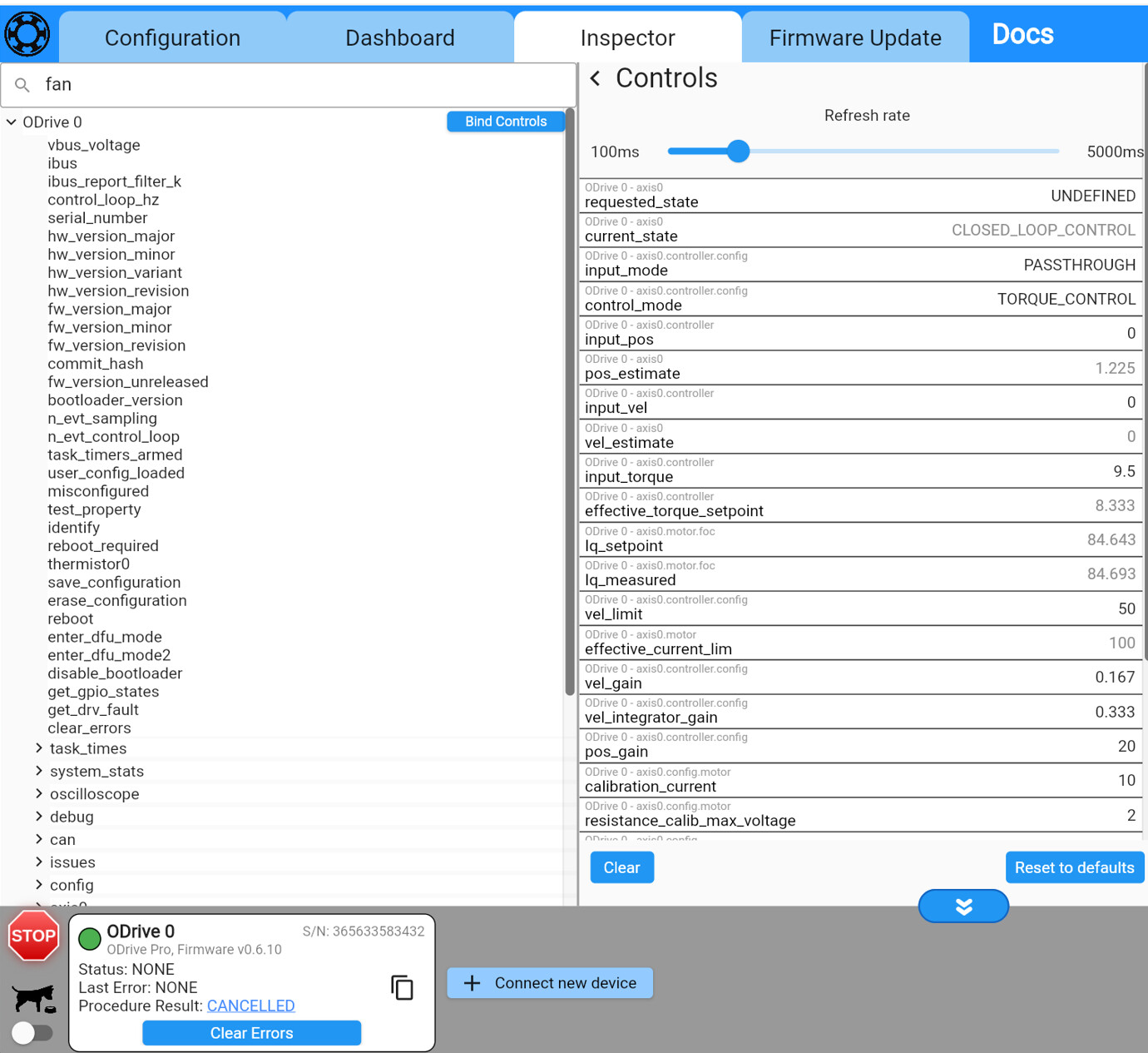
Hello, I am attempting to test my servo motor’s maximum instantaneous torque. Although I have set the current limit to 150 amps in the motor parameters section of the GUI, it appears that the Odrive Pro is limiting the current to 100 amps. Is there any way to output more than 100 amps for a short time such as 2-3 seconds?


image
image
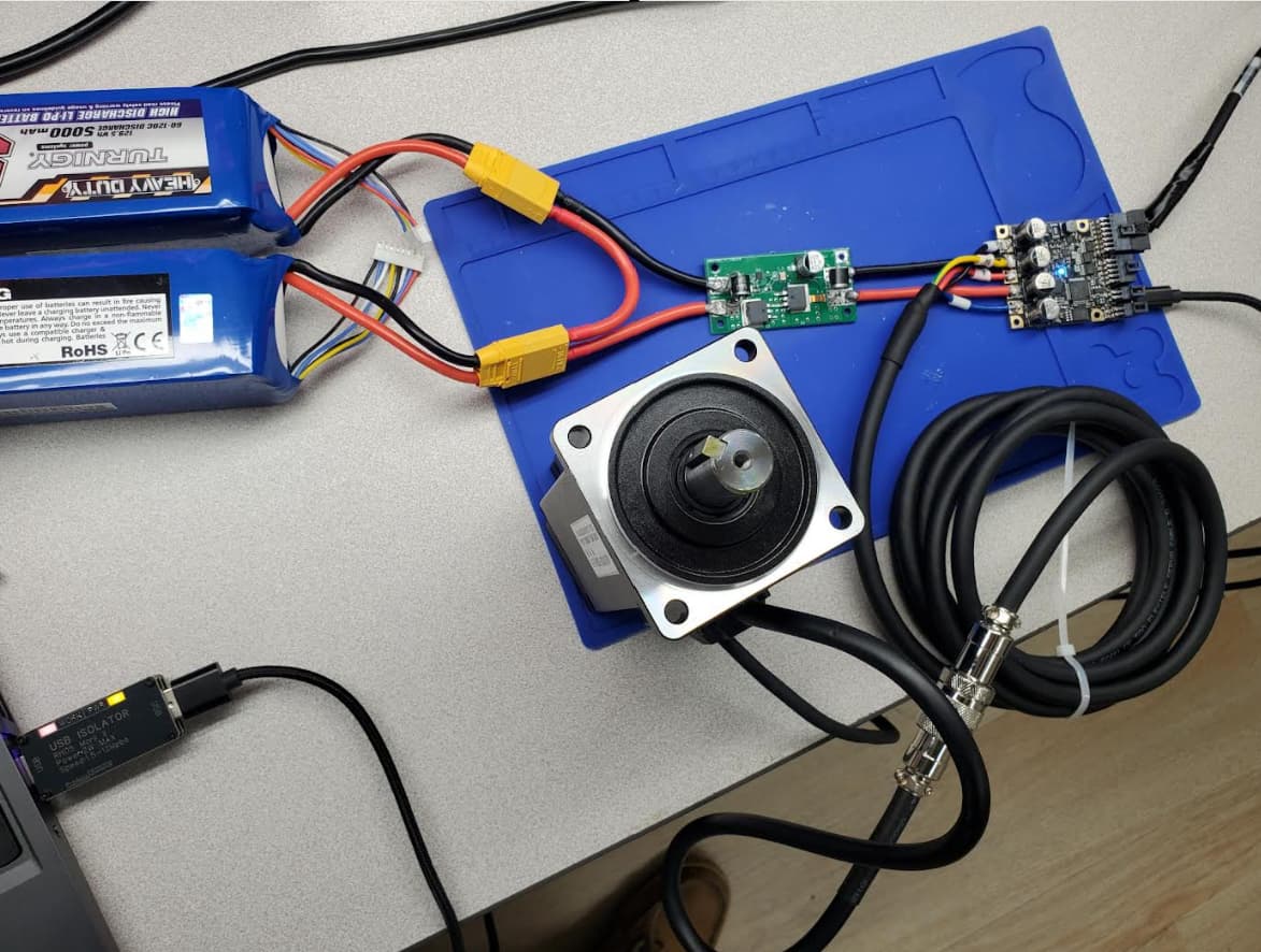
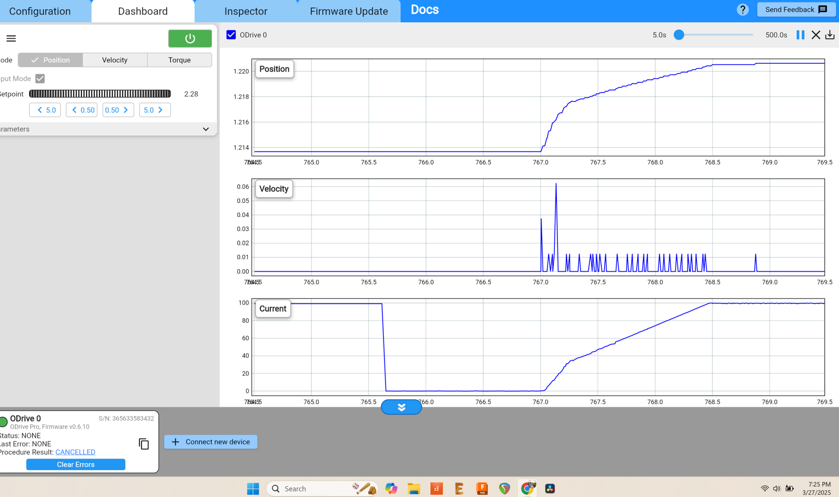
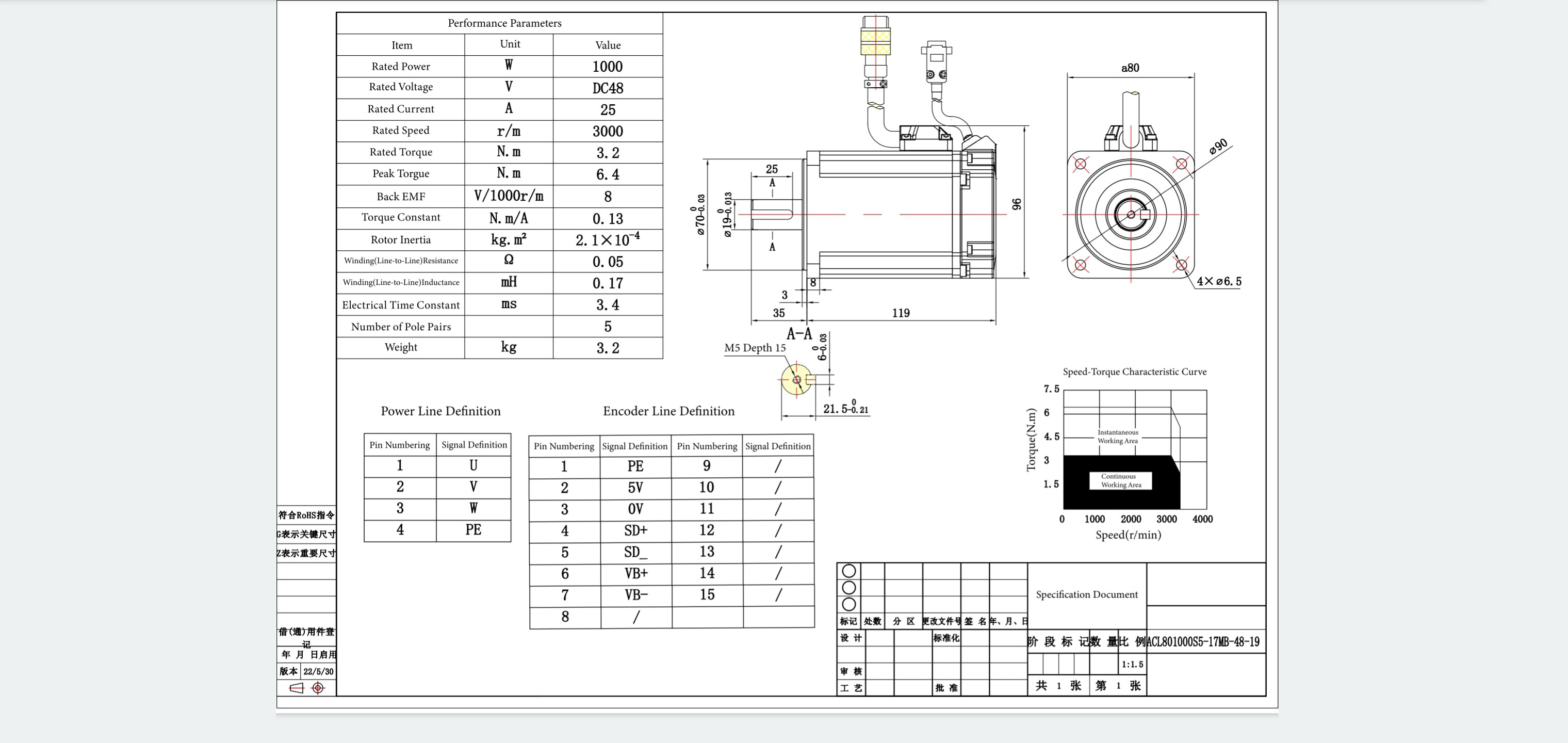
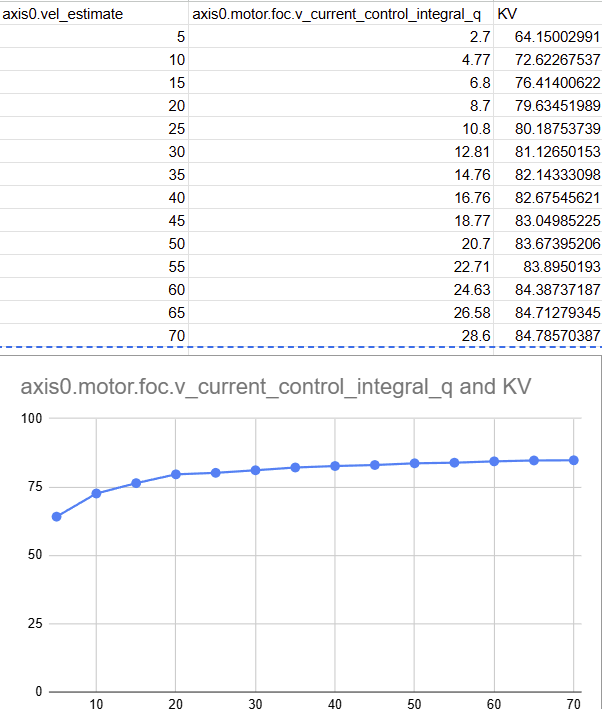
I think I have tried all of the different control modes already, but what is recommended for testing the max instantanous torque? So far my highest measured torque (externally using a scale and moment arm) has been 8.4 Nm and this is using position drive mode - the motor doesn’t turn during my test the torque arm is placed against a scale so as i increase the position the torque and amps ramp up but the motor cannot turn. 8.4 Nm is the torque measured externally when the GUI plots 100 amps. (Which also suggests that the advertised 0.13 Nm/A torque constant is wrong.
My clamp meter shows that the Odrive draws 30 amps from the battery when the GUI output shows 100 amps. Lastly my motor is rated for 48V and my supply (14s = [2 x 7s]) is presently charged to 54V. I was thinking that driving the motor with a slightly higher supply voltage could eek a bit more torque out of it; is there any validity to that hypothesis?
My motors rated torque is 3.2 Nm - its a standard 1000W/48V servo in an 80mm frame. The max instantaneous theoretical torque is 9.6. How practical is it that I could hit that 9.6?
Thanks!

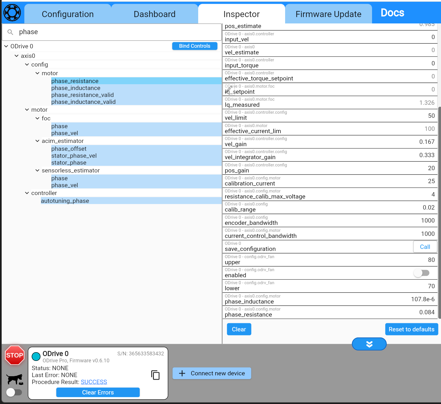
Edit: 2025-03-28; adding configuration text:
odrv = odrv0
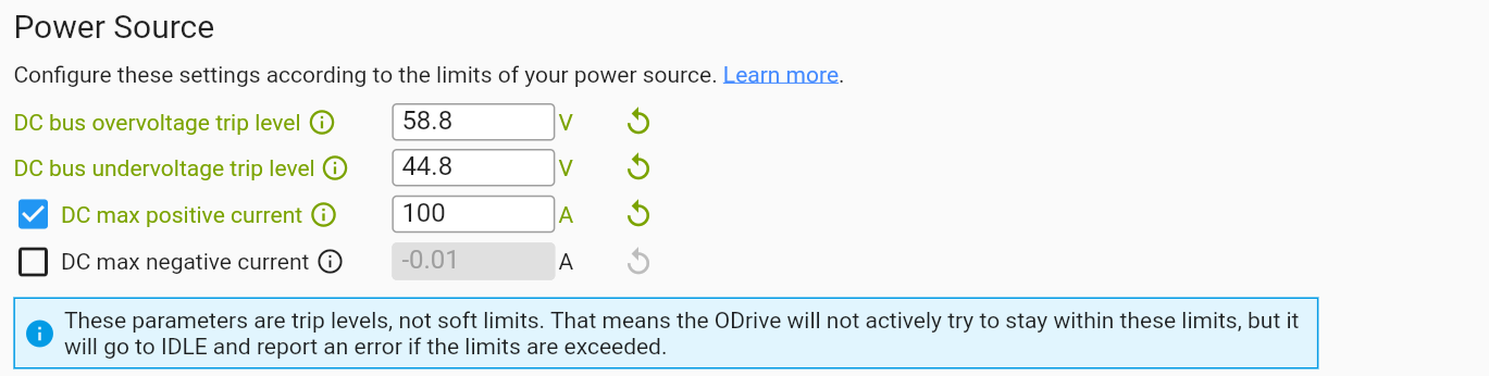
odrv.config.dc_bus_overvoltage_trip_level = 58.8
odrv.config.dc_bus_undervoltage_trip_level = 44.8
odrv.config.dc_max_positive_current = 100
odrv.config.dc_max_negative_current = -math.inf
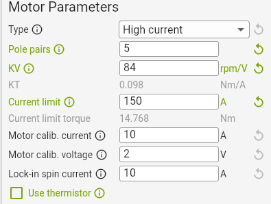
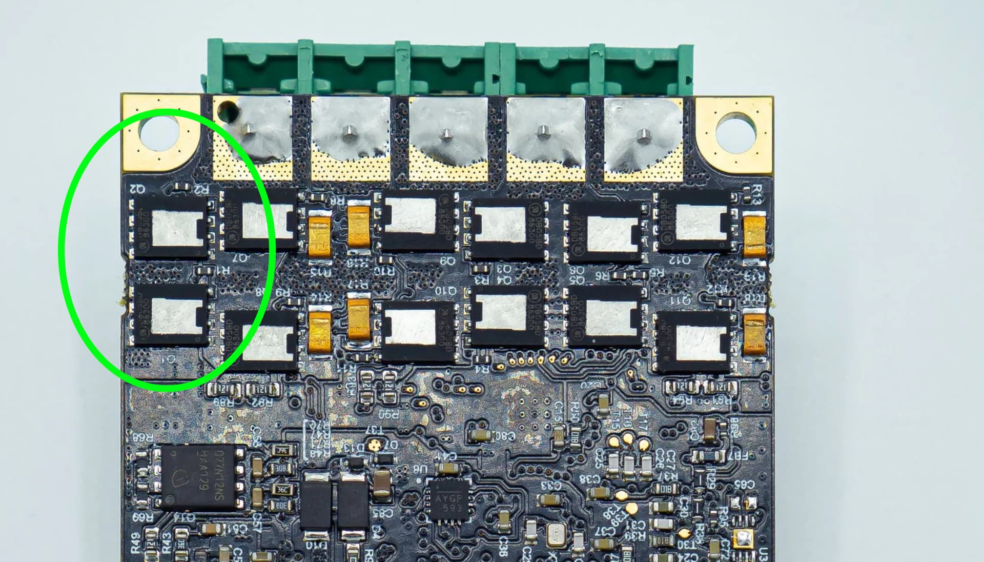
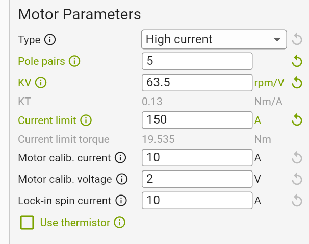
odrv.axis0.config.motor.motor_type = MotorType.HIGH_CURRENT
odrv.axis0.config.motor.pole_pairs = 5
odrv.axis0.config.motor.torque_constant = 0.13023622047244093
odrv.axis0.config.motor.current_soft_max = 150
odrv.axis0.config.motor.current_hard_max = 170
odrv.axis0.config.motor.calibration_current = 10
odrv.axis0.config.motor.resistance_calib_max_voltage = 2
odrv.axis0.config.calibration_lockin.current = 10
odrv.axis0.motor.motor_thermistor.config.enabled = False
odrv.axis0.controller.config.control_mode = ControlMode.POSITION_CONTROL
odrv.axis0.controller.config.input_mode = InputMode.PASSTHROUGH
odrv.axis0.controller.config.vel_limit = 50
odrv.axis0.controller.config.vel_limit_tolerance = 1.5
odrv.axis0.config.torque_soft_min = -math.inf
odrv.axis0.config.torque_soft_max = math.inf
odrv.can.config.protocol = Protocol.NONE
odrv.axis0.config.enable_watchdog = False
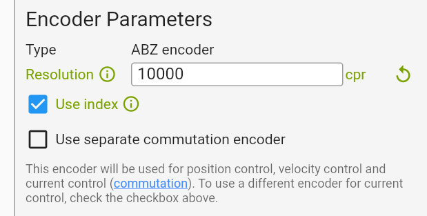
odrv.inc_encoder0.config.enabled = True
odrv.axis0.config.load_encoder = EncoderId.INC_ENCODER0
odrv.axis0.config.commutation_encoder = EncoderId.INC_ENCODER0
odrv.inc_encoder0.config.cpr = 10000
odrv.axis0.commutation_mapper.config.use_index_gpio = True
odrv.axis0.pos_vel_mapper.config.use_index_gpio = True
odrv.config.gpio7_mode = GpioMode.DIGITAL
odrv.axis0.pos_vel_mapper.config.index_gpio = 7
odrv.axis0.pos_vel_mapper.config.index_offset = 0
odrv.axis0.pos_vel_mapper.config.index_offset_valid = True
odrv.axis0.commutation_mapper.config.index_gpio = 7
odrv.config.enable_uart_a = False

Hi Mike,

Apologies for the delay in my reply.

My thoughts:

8.4 Nm is the torque measured externally when the GUI plots 100 amps. (Which also suggests that the advertised 0.13 Nm/A torque constant is wrong

This can be caused by one of two things – either your encoder calibration is incorrect, or the motor’s advertised kv/kt is wrong. Assuming you’re calibrating the motor under no load, the calibration is likely fine – most motor manufacturers fudge their kv/kt pretty hard, or use weird units. You can try boosting “Lock-in spin current” up to around 50-75% of the motor’s continuous current and retrying calibration, but I’d definitely expect it’s a kv thing here.

My clamp meter shows that the Odrive draws 30 amps from the battery when the GUI output shows 100 amps. Lastly my motor is rated for 48V and my supply (14s = [2 x 7s]) is presently charged to 54V. I was thinking that driving the motor with a slightly higher supply voltage could eek a bit more torque out of it; is there any validity to that hypothesis?

Motor current != supply current, they’ll only equal when the motor’s at maximum speed. Given this is likely a fairly low resistance motor (e.g. you’re not being limited by supply voltage in how much you can dump into the motor at standstill), raising the supply voltage won’t do anything.

Could you let me know the model number of your motor? I don’t know of any 80mm frame size 48V/1000W motors that would support more than 50-60A peak. Additionally, it looks like your ODrive isn’t being used with a heatspreader or heatsink – that’s strictly required for more than 20A continuous/40A peak. I’m honestly a bit impressed it didn’t blow up when you asked for 100A – doing so without any thermal management can heat the board faster than the onboard temperature sensors can detect and regulate it.

There are ways to unlock the onboard current limits on the Pro, but it comes with some considerations – and you’ll definitely need a solid thermal management system, at the very least a heatspreader+heatsink and fan.

Let me know that motor part number, and I’ll check it out!

Hi, Thanks for your reply.

Here’s the motor:


The peak torque is 3x rated torque, confirmed by the manufacturer. Similar motors are sold by stepper motor online https://www.omc-stepperonline.com/dsy-series-1000w-rs485-dc-servo-motor-24-70vdc-3-20nm-3000rpm-17-bit-incremental-encoder-ip65-dsy-rs1000l2a2-m17s , Leadshine, and many others. The peak torque is always indicated as 3x rated (9.6).

The encoder datasheet indicates 2500 C/T. I thought that was counts per turn but the odrive configurator rejected 2,500 cpr and suggested 10,000 cpr. I assume those numbers are related by a quadrature relationship. With 10000 cpr the position control works correctly.

Thank you yes I know I need a heat spreader and fan. I will buy them asap. (Edit 2025-04-03 10 @ 14:23 UTC: I purchased the fan and enclosure Order #12614) I provided the input amps only for reference; I read the article that was linked in this forum about supply current vs motor current last week. In fact I read it right before I almost returned my clamp meter because I thought it was broken, lol. I also designed my LTC 4368 board to take momentary 120 amps because when I was creating the PCB I thought supply and motor current would be the same - oops. Anyway thanks for your advice on this IC I love the protection it offers and now its overdesigned.

The motor manufacturer did not provide the KV. I calculated it as 3000 rpm / 48V = 62.5 KV

Yes, I want to unlock the current limits. Yes I understand I will probably break the odrive. I accept the risk and take responsibility.

Hi Mike,

Awesome, thanks for the motor datasheet.

Yeah, “peak torque” always seems to be vibes based, and not actually a number associated with a specific duty cycle, haha.

The encoder datasheet indicates 2500 C/T. I thought that was counts per turn but the odrive configurator rejected 2,500 cpr and suggested 10,000 cpr. I assume those numbers are related by a quadrature relationship. With 10000 cpr the position control works correctly.

Correct, encoder counts = 4x encoder pulses, manufacturers love to be ambiguous as to if they’re specifying counts or pulses.

Great to hear you like the LTC4368, it’s a nice lil chip :slight_smile:

The rated speed of the motor (3000 RPM) is typically the speed the motor can achieve at the rated torque of 3.2Nm.

If we take their back-emf constant of 8V/1000RPM, that gives us a KV of 125 RPM/V. However, if we take their rated torque @ rated current, that gives us a KV of 8.27/(3.2/25) = 64 RPM/V. Definitely some discrepancies here :slight_smile:

If we assume instead that’s V_rms and A_rms then that’s 88 KV from the back-emf constant, and 91KV from the rated speed/torque – that lines up a bit better. Plus, that matches if we assume their stated torque constant is in Nm/A_rms instead of Nm/A_pk (which the ODrive uses) – 0.13 Nm / (sqrt(2) A) = 0.09 Nm/A == 90KV (convert from rms to peak voltages by multiplying by sqrt(2).

So I’d generally say that the actual KV is going to be about 90 RPM/V, and actual torque constant around 0.091 Nm/A. That means for a peak torque of 9.6Nm, you’ll need about 105A.

I’m then surprised you’re only getting 8.4 Nm at 100A, so that then makes me wonder if the encoder calibration is a bit off. Additionally, 30A from the supply should not correlate into 100A into the motor at standstill with a 54V bus voltage and the datasheet’s stated phase resistance, so there’s something off there.

A few questions/asks:

  1. Can you try bumping the calibration current to 25A, keep the calibration voltage at 2V (raise this to 4V if you have resistance or inductance calibration errors), and bump the lock-in spin current to 25A, then go through calibration again.
  2. After that, go into the inspector tab and search for “phase_inductance” and “phase_resistance”, drag those values to the center, and let me know what they are.
  3. You can also retry the torque measurement at 100A to see if this was an encoder calibration issue (please wait on the heatspreader+heatsink to do so for this step)

There’s also a fairly straightforward way of experimentally determining the motor’s kv value:

  1. Spin the motor unloaded in velocity control, at some medium-high speed in velocity mode

  2. Make sure you’re well below saturation (maximum) speed, I usually do around ~half of the motor’s theoretical maximum speed, and try a few different points along the speed range to ensure consistency

  3. Measure the velocity in rev/s with axis0.vel_estimate and look at axis0.motor.foc.v_current_control_integral_q

  4. KV will be roughly 60*vel_estimate / (sqrt(3) * v_current_control_integral_q)

  5. for example, if you’re spinning at 30 rev/s and v_current_control_integral_q is 8.73, then that’s a KV of 60*30/(sqrt(3) * 8.73) == 1800 / (1.732*8.73) == 119 RPM/V

I’m also going to give the precaution that the 1kW rating on the motor is the mechanical power output – e.g. 3000 RPM * 3.2Nm = 1kW. It’s definitely not the actual heat power the motor can take, given their rated stated resistance and rated current, it looks like they’re saying the motor can take about ~62W continuous. When you’re putting 100A into it, that’s 500W in power dissipation, which I would be very careful to do for more than half a second to a second or two.

Let me know how all that goes! If you’re still not able to hit the 9.6Nm figure at 100A, I can email you the unlock instructions.

Thanks again for your support. I installed the enclosure and fan and it is running as expected.
Good news to report:
I followed the suggested procedure and plotted the resutls below. I selected a KV of 84 rpm/V.


I updated the KV in the configurator (84 KV; resulting in KT = 0.098 Nm/A):
image
Using the position control dashboard, a torque of 9.5 Nm was measured (with the current still limited to 100 amps). This is a very strong result: [(9.5 - 0.098*100)/9.5] x 100 = 3% error. I’m not concerned about this error - perhaps I could reduce it by adjusting the KV but for now I’m very happy with the result.

The only topic outstanding is the Torque Control Mode: When I switch to torque control mode and go go the torque control dashboard and enter 9.5 Nm, I expect the output torque to be 9.5 Nm and the motor current to be 100 amps (just like in Position Control Dashboard), but the output is about 8.2. This seems to be closely aligned with the “effective_torque_setpoint” (8.33) but I do not know why because I do not have a torque limit enabled in the configuration. Can you share guidance on how to yield torque output that is equal to (100%) of the input_torque?

Lastly, though I don’t think it was needed I did recalibrate using 25A calibration current, 4V calibration voltage (needed to raise it from 2V), and 25 A lock-in spin current. Results are below. I did check the output torques again after the recalibration and they remained 9.5 Nm via Position Control Dashboard and 8.2 Nm via Torque Control Dashboard with 9.5 Nm torque input.

Great to hear you’re making some progress!

When I switch to torque control mode and go go the torque control dashboard and enter 9.5 Nm, I expect the output torque to be 9.5 Nm and the motor current to be 100 amps (just like in Position Control Dashboard), but the output is about 8.2. This seems to be closely aligned with the “effective_torque_setpoint” (8.33) but I do not know why because I do not have a torque limit enabled in the configuration

enable_torque_mode_vel_limit uses vel_gain to limit the torque. At high torques it can be limited even at zero speed, see: Controller — ODrive Documentation 0.6.10 documentation

You can disable enable_torque_mode_vel_limit, or you can tune your vel_gain.

Hello, When I disabled enable_torque_mode_vel_limit the torque control dashboard worked as requested: outputting roughly 9.5 Nm @ 100 amps. Then, I turned it back on and attempted to adjust the vel_gain in small increments but I have encountered a persistent error:

DRV_FAULT.

{
“serial_number”: “365633583432”,
“fw_version”: “0.6.10”,
“commit_hash”: 3621886066,
“product”: “4.4.58”,
“active_errors”: 0,
“active_errors_str”: “NONE”,
“disarm_reason”: 32,
“disarm_reason_str”: “DRV_FAULT”,
“procedure_result”: 3,
“procedure_result_str”: “DISARMED”,
“last_drv_fault”: 2098432,
“internal_issues”: 0
}

I have attempted two full power diconnect/reboots and the issue persists so I beleive this indicates damage to the driver or FETs. I ordered two new Odrive Pros #12689.

In the meantime, is there any troubleshooting I can do and/or can I replace the driver or FETs? I have a hot air rework station, etc. Thanks!

Huh, that’s not great. This is with 12S LiPo + Pro on a heatspreader, with the green thermal interface material?

Hi, This was with a 14s and an Odrive Pro with the enclosure and fan; thermal interface material installed between fan and enclosure. The fan was running because I lowered the threshold to ensure it was on. The battery was charged to 55V. The Odrive was cold. I believe the failure occurred when the rotor was stopped suddenly during a collision.

Oh interesting. Specifically, wanted to check if the green thermal material was installed between the Pro and the enclosure:

That being said, could you tell me a bit more about the collision? Approximately what speed was the motor operating at, and was the ODrive actively driving it? If so, about what current was going through the motor?

No, that wasn’t where I placed the thermal pad. Thanks for letting me know the correct placement; I’ll be sure to assemble it there in the future. That might have contributed to the issue, but I don’t think so, since the ODrive was cold, started and ran for less than a second, and then experienced a collision and failure. I don’t believe there was enough time for any significant heat buildup or dissipation.

My experiments with the ODrive have primarily focused on testing servo torque at 0 RPM. I stop the test after only a second or two—just long enough to take a reading from the scale. (I’m using a moment arm of known length and a scale to measure torque.)

I’ve been working to determine the maximum torque of my motor, and subsequently, the gearbox. First, I measured the max torque of the motor. With your help, I dialed in the KV. At 100 amps, the motor torque was 9.5 Nm. However, I was only getting 100 A / 9.5 Nm in the Position Control Dashboard. I suspect that enable_torque_mode_vel_limit might be disabled by default in the Position Control Dashboard.

Regardless, once I disabled enable_torque_mode_vel_limit, I was able to observe 9.5 Nm and 100 amps in the Torque Control Dashboard—another success. I then re-enabled enable_torque_mode_vel_limit and adjusted vel_gain in small increments until I could again achieve 9.5 Nm and 100 amps with enable_torque_mode_vel_limit enabled.

Next, I assembled the motor to my 50:1 harmonic gearbox. When I ran the same test, the output torque was only 380 Nm instead of the expected 475 Nm. I thought I might need to tweak vel_gain, so I made some adjustments. On the subsequent test, the error occurred. I’m not sure if the failure was due to the vel_gain change or because of the “collision” that happens when the gearbox test is run. (For context, I’ve run the test multiple times with the gearbox, and I’m confident the output ratio is 50:1. However, this was during earlier tests when the KV was 63.5 and 100 amps yielded only 8.4 Nm.)

To test the gearbox output, I attach a 7-foot-long moment arm to the gearbox output and connect the end to a fish scale. The scale reads force in lbf, which I multiply by the arm length (7 ft) to get moment in ft∙lbf, then convert to N∙m.

There’s some slack in the fish scale when the motor is off, due to the flexible lead on the hook (example below):


The moment arm rotates approximately 5 degrees before the slack is taken up. Given the 50:1 gearbox ratio, this translates to 250 degrees of motor rotation. To run the test, I was in the Torque Control Dashboard, input 9.5 Nm, and hit enter. The moment arm then jerks forward, and the scale displays a force that usually holds for 2–4 seconds. I’m not certain of the motor speed during the 250-degree rotation, but I estimate around 10 rev/s. The rotation lasts only a fraction of a second until the “collision” (when the slack is taken up and the arm is suddenly stopped).

I ordered two new Pros Order #12689 but I do need three for my project so I was hoping you might provide the part codes for the ICs and I can take a run at replacing them.
I’m creating the first leg of a 12 DOF quadruped so starting with three and then hopefully ordering 9 more after testing the leg.

I ordered two new Pros Order #12689 but I do need three for my project so I was hoping you might provide the part codes for the ICs and I can take a run at replacing them.

FETs are FDMS86300DC, gate driver is DRV8353S. Your DRV fault indicates a gate drive fault on the high-side FETs on phase A, which would be Q1 and Q2:

That being said, happy to replace this under warranty – this is the sort of failure that I very very rarely see on an ODrive Pro (the field failure rate is effectively zero), and would be interested in getting the unit back for diagnostics.

Could you let me know where the thermal pad was placed? A picture of the pad residue on the Pro (when disassembled from the enclosure) would definitely be helpful. My thinking is that even if the unit was cold, the thermal mass of the FETs is quite low, and a local hotspot created by the large current spike, combined with incorrect thermal pad placement, could lead to the FET getting real hot and desoldering or damaging itself.

I’m embarrassed to admit it, but as I mentioned yesterday I installed the thermal pad between the aluminum enclosure and the fan sink. I thought it was to facilitate heat transfer from the enclosure to the fan sink. In retrospect in makes sense for it to be in contact with the FETs, but I’ve never used thermal pads/paste. I did not find assembly instructions for the fan and enclosure and looking at the CAD from a bad angle reinforced my incorrect assumption that the pad was between the enclosure and fan sink.

If you would like me to send the unit back for diagnosis and replacement please provide instructions. Otherwise, I will try to replace Q1, Q2 and the driver.

No worries whatsoever! Shoot me an email at solomon.greenberg@odriverobotics.com.

Definitely agree we need better assembly instructions, that’s something we’re working on :slight_smile: