So, I have had my motor running in sensorless mode for a while now, but recently the wires I needed to connect my hall-sensors arrived. So I have tried configuring them, but without any success.
What I have:
I am getting encoder error 0x10, which means i have an illegal state.
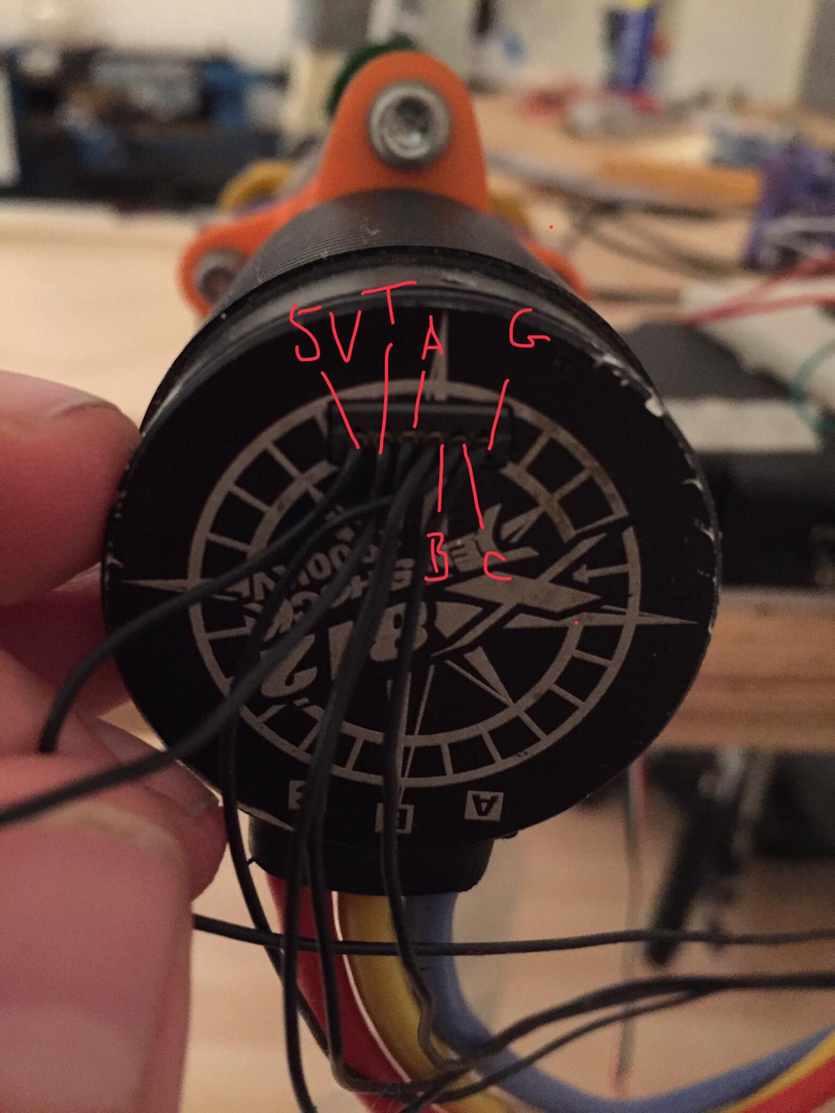
when I test the hall sensors manually, they appear to nicely move through the quadrature like I would expect, never producing 000 or 111, always at least one sensor high and one sensor low.
when I manually supply the sensors with power and ground, the pins that I want to plug into the Odrive read ABC = 110 (1 = 5V, 0=0V). However, when I plug it in and measure the pins I get everything at 4V so ABC=111.
The 5V, 3V, and Ground are still functioning normally.
Have I blown up the chip? Or is there some setting on my Odrive set wrong?
So I measured the resistance between the ABC/Z pins on my Odrive and they are around 6.6kOhm. That seems to indicate a short right? The resistance between two random GPIO pins on the Odrive is 288kOhm.
Thanks for pointing them out. I have seen them, and I don’t think capacitors will solve my issue. Capacitors would help filter in a noisy situation, but at the moment my issues is when the motor is static.
The problem I have is that the ABC/Z ports on the Odrive should be low, so that the active hall sensors can pull them high.
I am trying to figure out if the ports are working as intended, and i need to change my configuration somehow. Or if the ports are broken, and I need to get the unit replaced.
Basicly the Odrive is forcing ABC/Z to high, which is an illegal state.
I would try 22nF capacitors anyway, it is easy and believe me i spent lot of time figuring out why it is not working and those caps saved me:) Without caps it is completely strange behaviour it does not matter if your motors are spining or not, just completely strange:)
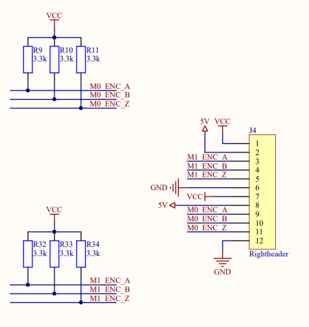
We have pull-up resistors to 3.3V on the encoder inputs, because many encoders (and hall signals too) are open drain. It seems you have push-pull sensors since you can see the output when disconnected.
Usually push-pull encoders/halls will drive over the 3.3k load just fine. However if you but if your motor’s sensors have really weak output current (<2mA) I guess they could have issues. You can try to de-solder the pull-up resistors and see if that helps.
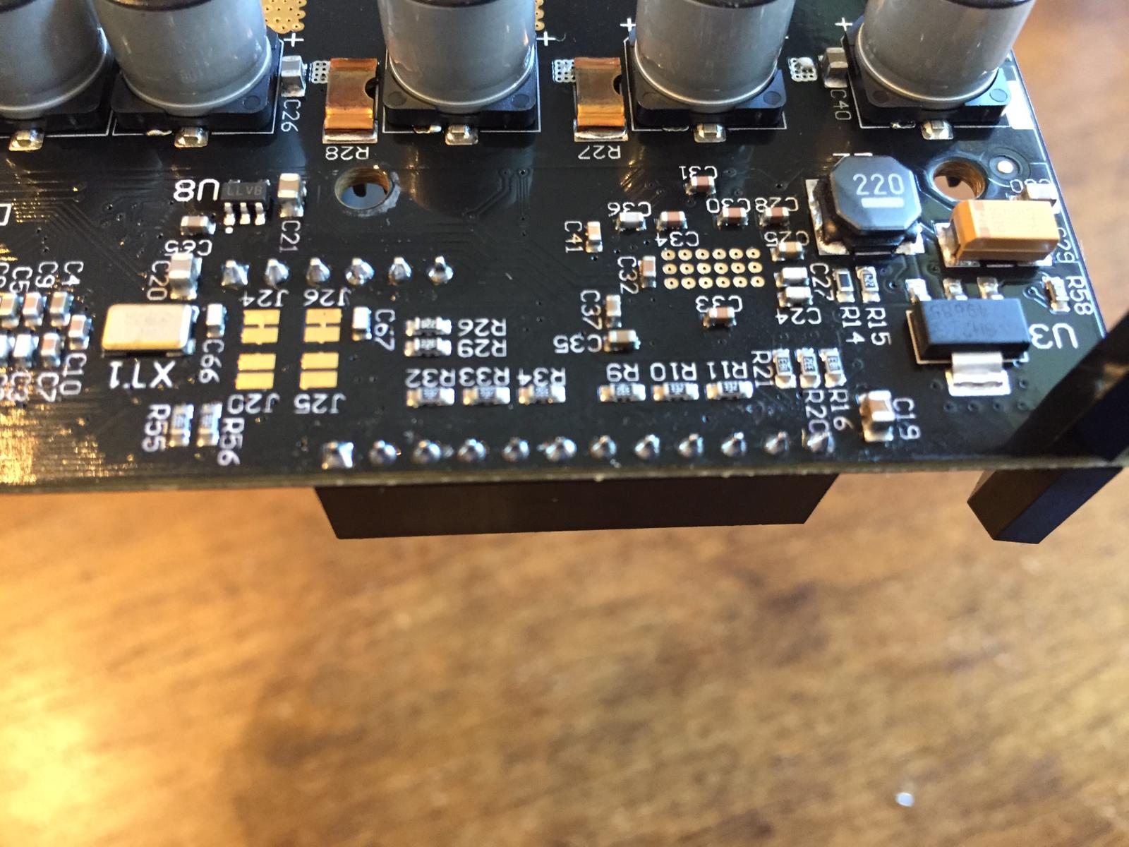
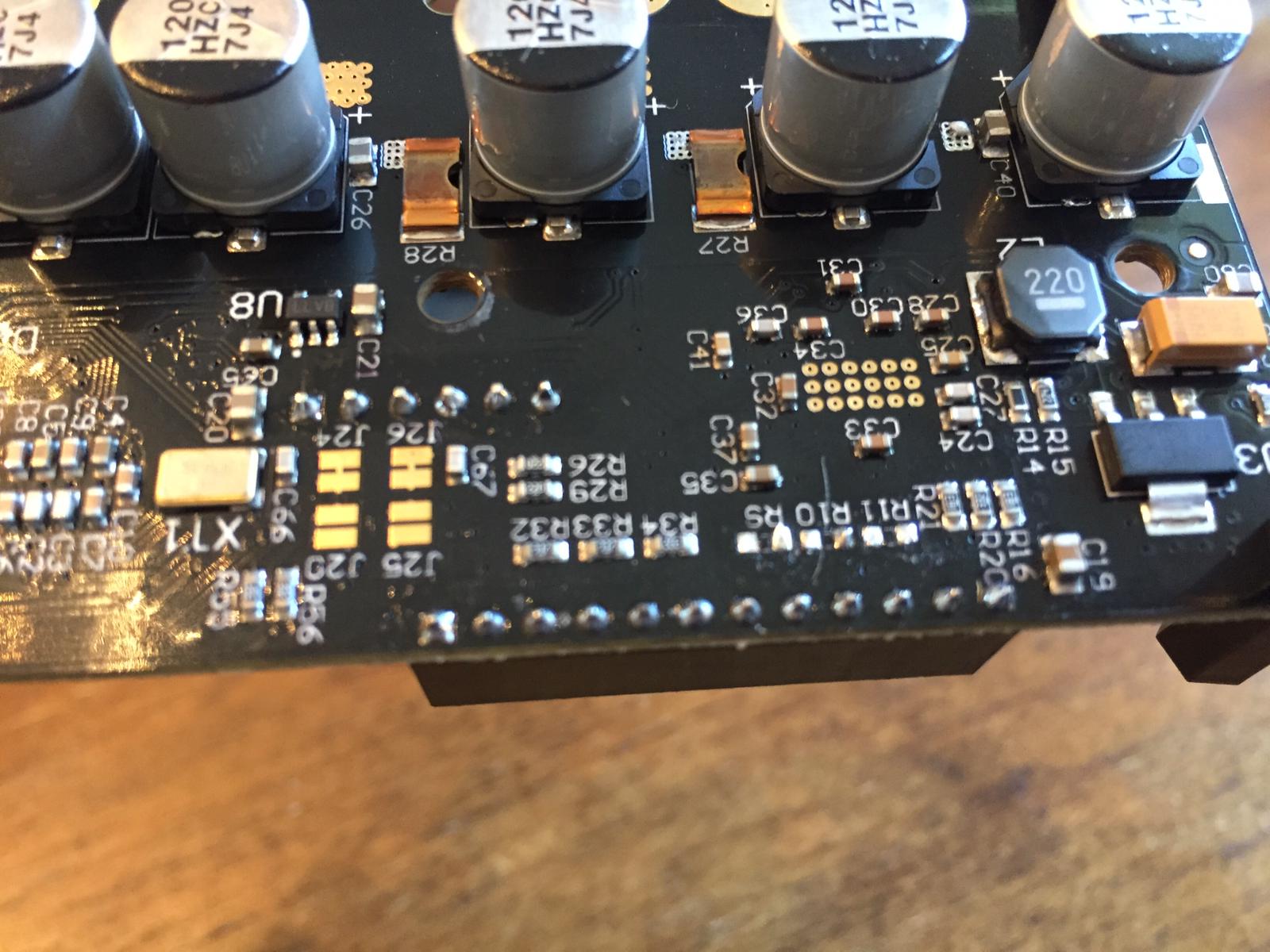
They sit on the back of the board right next to the encoder input. Check this part of the schematic for the designators:
If you still wanted to stick in the 22nF caps, a capacitor to ground is roughly equivalent to a capacitor to VCC, therefore you could use the same pads to install the caps. Convenient! S.
Hi there! Found this thread several years later because I may be having the same issue, but I’d like to check. How did you measure your 0.42mA number on the hall sensors? Not quite sure what to hook up my multimeter to and where to measure the current. Thanks for any advice!
I actually got it working today! Well, on Axis 1. Axis 0 the hall encoder doesn’t seem to read at all. Tried with 2 motors - both show nice hall states when plugged into axis 1, but neither show anything but 0 on axis 0. I assume something’s wrong with the ODrive, that means I’m fairly comfortable with circuits, but lack more than the basic tools to try and diagnose. If anyone has any places to start, I’m all ears!
Another update - used my multimeter to check the encoder header pins against the STM32, and everything there seems normal too. I see continuity on M1A/B/Z to the appropriate STM32 pins, and same for M0A/B/Z. This is with the ODrive powered off, for context, but it seems the hardware is okay. none of the 6 resistors on the back connected to the encoders are shorted; one side of each ties to 3v3 and the other side ties to the encoder pins.
This gives me hope that the Odrive is okay, but doesn’t explain why I can’t get any readings on axis 0 while axis 1 is totally fine.
I think I have a fairly standard multimeter, nothing special. It has a mA setting. I guess you could also use a known resistor, and measure the voltage drop across it?