Turning a Mill into CNC to help with an electric car conversion

Hi @towen,

Yeah, the full front is a door, making a video at the mo of how I made it, should be out in the next few weeks.

My wife and kids love it, think my wife is a secret engineer as she suggested it came into the lounge to prevent it rusting :wink:

The device is a 1000W pure sine wave inverter from Bestek (not Bestech, edited), it uses 1A itself so does increase the drain on the batteries. The spindle motor, cabinet lights and chip blower pulls around 170W in total, where the Z and X axis drive pulls around 1A each when moving at full chat. So all in all on the 75Ah battery from full charge lasts around 4 to 5 hours, although I’m only getting a low charge from the 50W solar panel with the UK sun, so running the spindle motor from the wall at the mo (although I am with a 100% renewable energy company for home energy, so still green).

I have used it as a UPS on the computer when video rendering during a power outage, plus it was running our fridge freezer also.

What sort of parts are you after for your mill?

1 Like

Hi all,

Thought I’d share this as it may be helpful for someone…

Ok, I had a fun night last night with the following on axis0 only: -

ERROR_CONTROLLER_FAILED
ERROR_CONTROL_DEADLINE_MISSED
ERROR_OVERSPEED

Think I may have been getting some noise on the encoder lines :thinking:

I haven’t had this before, but I did change a few things recently that may have caused this to show up (increase noise).

  1. I added 2 x 12v cooling fans to my spindle motor, this may be adding to the noise, although still happens when switched off.

  2. Increased tension on the Gib strips to increase accuracy.

No.2 is where I believe the issue is coming from indirectly, where the motor is under slightly more load, therefore increasing the magnitude of the noise of the PWM signals and now interfering with the encoder.

I don’t yet have the motor cables twisted to cancel out the noise, nor do I have any shielding between the encoder cable and motor cables. In fact the encoder cable and motor cable are hugging each other for 0.5m up to the ODrive, (not ideal, but works ok with low current). The motors are only pulling around 750mA when moving and around 40 peak during acceleration from 0rpm, where the error only happened during a move.

I will be re-arranging my cabling, using cat-6 cable for the encoder and adding a twist to the motor cables, although just needed to get it reliably going again, so I did the following: -

  1. Re-tuned both X and Y axis motors in accordance with the online the guide (due to the change in load). This reduced the frequency of the error, although did was not a direct fix.

  2. Reduced the motor.config.current_lim on both motors to 10A. This did nothing to the error, I was just meaning to do this for a while and made sense to do it now. It may have reduced noise a little (not sure as have no access to spec anny).

  3. Incrementally increased the velocity limit ratio under odrv0.axis0.controller.config.vel_limit_tolerance from 1.2 up to 2. I went through 1.2, 1.3, ect, and tested until it failed, where it was stable at around 1.8. So I set this to odrv0.axis0.controller.config.vel_limit_tolerance = 2

I have had no errors at all today with it running for the full day (touch wood). I still believe this to be a noise issue and will reduce this value again once I put some better noise control measures in place, especially when I attach the brushless spindle motor :wink:.

I hope this helps someone.

Happy ODriving,

Neil.

Edited: P.S. I have a 24v v3.6 board runing v0.4.11

2 Likes

Grab a couple of these ferrite rings https://odriverobotics.com/shop/n97xgxel6y0ufvunsxq70kih4p19nx

They make a huge difference.

2 Likes

Thank you @Wetmelon I will order a few of these today.

I may only be able to achieve 1 turn due to having 8AWG cable, but 1 turn is better than none :wink::+1:.

You could always get a bigger one :slight_smile:

1 Like

Or that one… :+1:

Either way I should have done this at the start. It will become more relevant when the spindle motor is active.

Just thought you’d like to see my latest creation, purely machined out using my ODrive CNC machine with only manual Z-Axis movement every now and then… (I’m slowly making myself redundant :wink:)

I’ll be uploading a full video of the machine milling out all the parts at some point, hopefully in the next few weeks. The Z-Axis and spindle are coming along nicely too.

Hope you enjoy.

Happy ODriving,

Neil.

3 Likes

Hi Neil, hope you’ve had a Merry and safe Christmas for all your family, and thanks for the nice little creative video for us all to enjoy.

Glad to see the spindle and Z axis is coming along.

So Neil, keep on staying safe and have a Happy New Year :partying_face:

Regards Jerry :australia:

Hi Jerry, we have had a great Christmas thank you, albeit a quiet one, but sometimes that’s nice too. Hope you and your family have had a good and safe Christmas too.

Happy New Year :confetti_ball:.

Kind regards,

Neil.

Awesome stuff! Merry Christmas

If you don’t know the scene: old school. You wanna see the movie…

Cheers Quintin, Merry Christmas.

Maybe this toy can re-enact the scene :grin:, although it’s on its way down to my nephew as we type :thinking:.

Hi all,

Hope you are all well, just thought I’d give an update.

I’m still doing things in the background, although have been very busy with my day job, will be changing jobs later this month and moving house (huge task when you have 2 littlen’s). Still on track, the next house has a garage… so the milling machine will move to there, this is good news as I can run it at max speed without worrying about swarf on the carpet, doh!.

So as the machine is packed up I’m getting into the video editing side again and planning the MGF build, where I now have a towbar fitted to my car and a twin axel trailer to transport the MGF.

What is next? Well I still have to finish off the Z-Axis and spindle, although this should be a lot easier in a garage, then it’s directly on to the MGF build.

I want to do a lot more with the ODrive’s in future and am now seriously looking to use them in the MGF. I may even turn up at the Birmingham NEC with it late in the year, that is my altimate short term goal anyway (charred or charging), watch this space.

Happy ODriving,

Neil.

4 Likes

Hi Neil, I wondered where you where, and hoped all was well in your part of the world, I guess Job, and moving would explain your absence.

Yes everyone need a shed/garage mostly for sanity sake, or at least that has been my experience.

Here is something that may interest you for MGF’s future, that is you didn’t know already.
https://fullycharged.show/ let Robert know and I’m sure the show will have interest :slight_smile:

Anyways just glad to hear you are still moving forward.

Regards Jerry. :australia:

1 Like

Thank you Jerry, all is well here.

Looking forward to the garage.

I was a Patron of Robert for a good while and have mentioned it on a few occasions although think the team are really busy and I can’t get the MGF up and running quickly due to the day job :grimacing:.

Hopefully things will move quicker this year.

Kind regards,

Neil.

Very inspiring project Neil, it answers lots of questions to me which I consider in my cnc build, and sure interested to see your experience with BLDC spindle as I plan the same just with little bit more powerful 6384 120KV BLDC. One question, is 5065 powerfull enough for axes? Will it drive 2x bigger cnc?

For your car, might be better to look out at Vesc project? First of all it is more suitable for such aplications, and second there are several high power projects available to the public, you may order your PCB and build your self one which will cost you less then buying one…

1 Like

Hi all,

Hope you are all well.

I’m back, in a new house, with a new day job, after a heart op and now have the garage set up and started creating content.

This is my garage setup…

Although the video I’ve just uploaded was made in the old house. Here it is though: -

Now I’ll be able to get on with the Z and spindle drives.

Happy ODriving,

Neil.

4 Likes

Hello all,

I hope all is well.

I’ve been busy getting a new PC for video editing, getting on with a long edit (the video below) and tweaking the design of the Z and Spindle parts to machine out.

I can’t say how happy I am with the ODrive system. The accuracy allows me to create parts near perfect dimensions and repeat them with negligible deviation.

Here is my latest video: -

Hope you enjoy it.

Happy ODriving.

Neil.

Hello all,

Hope you are all having a good weekend.

I know I haven’t posted in a while, so thought I’d give an update and share the CNC mill development so far, basically, I’m now going to control the ODrive with a Teensy 4.1 and use a Gameduino 3x Dazzler to display on a Portrait oriented HDMI display.

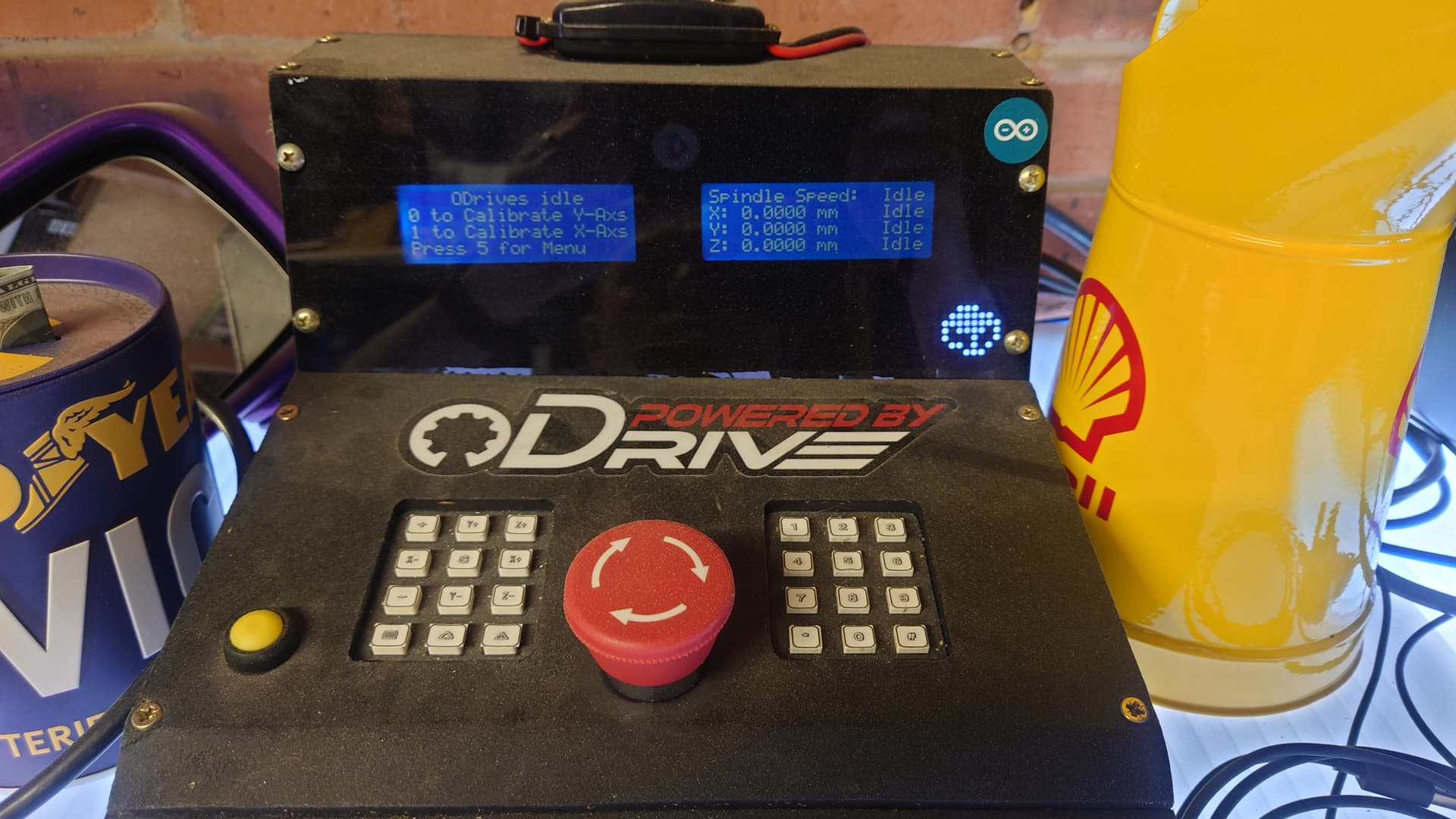
Ye Olde controller that can be frustrating to use…

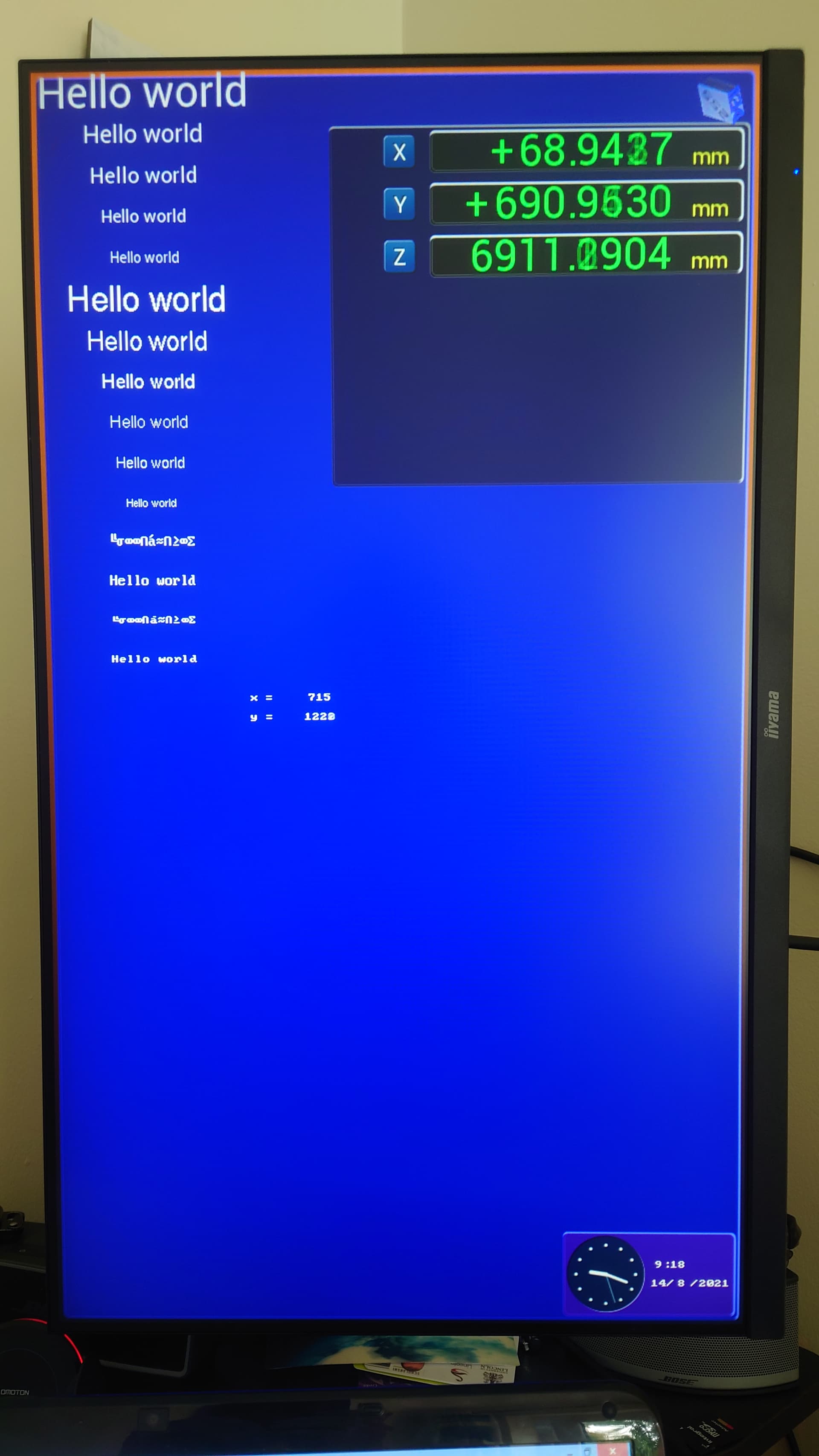
New Display using the Teensy 4.1 controlling the Gameduino 3x Dazzler…

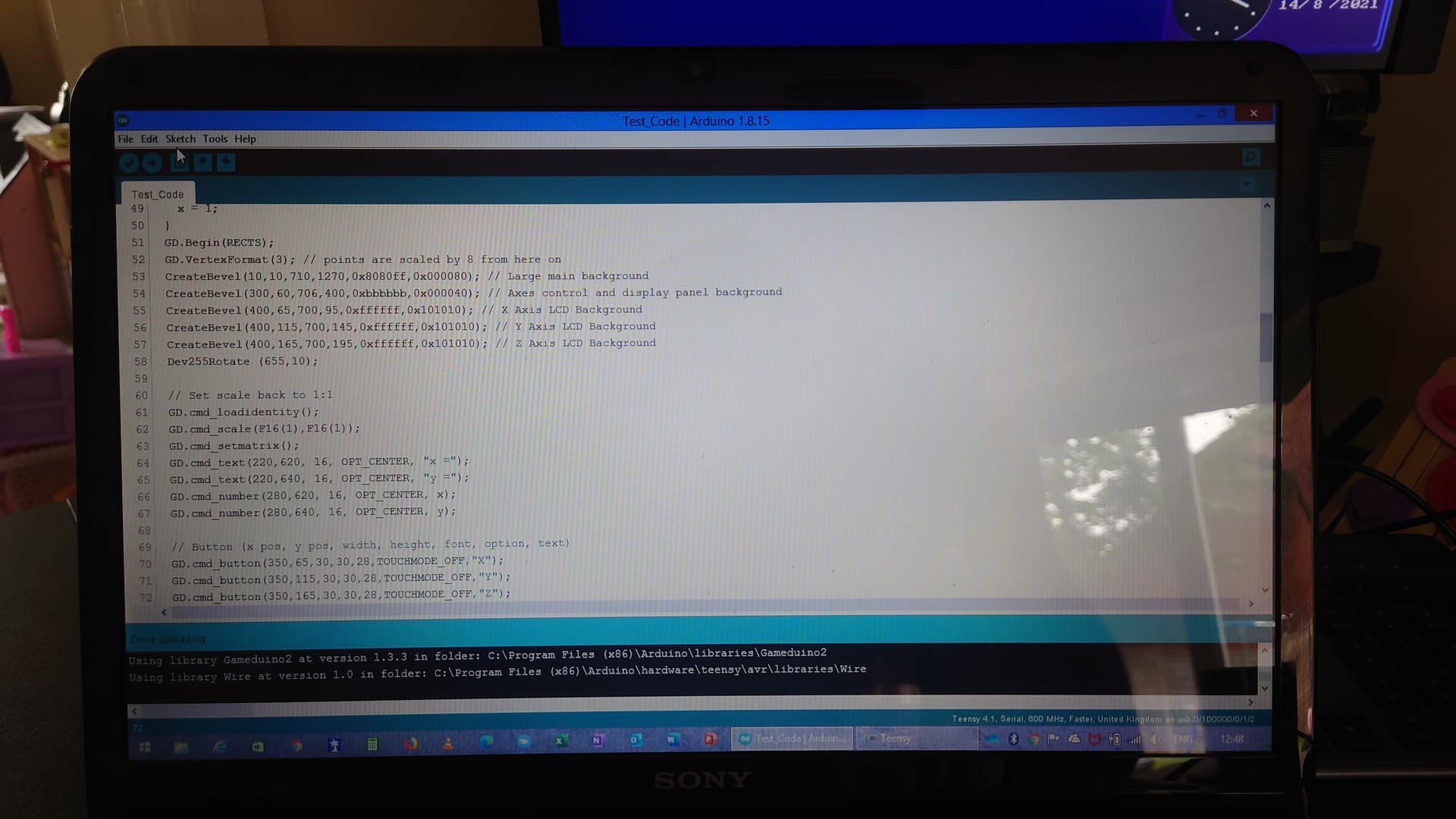
Programming the Teensy (easier than I thought).

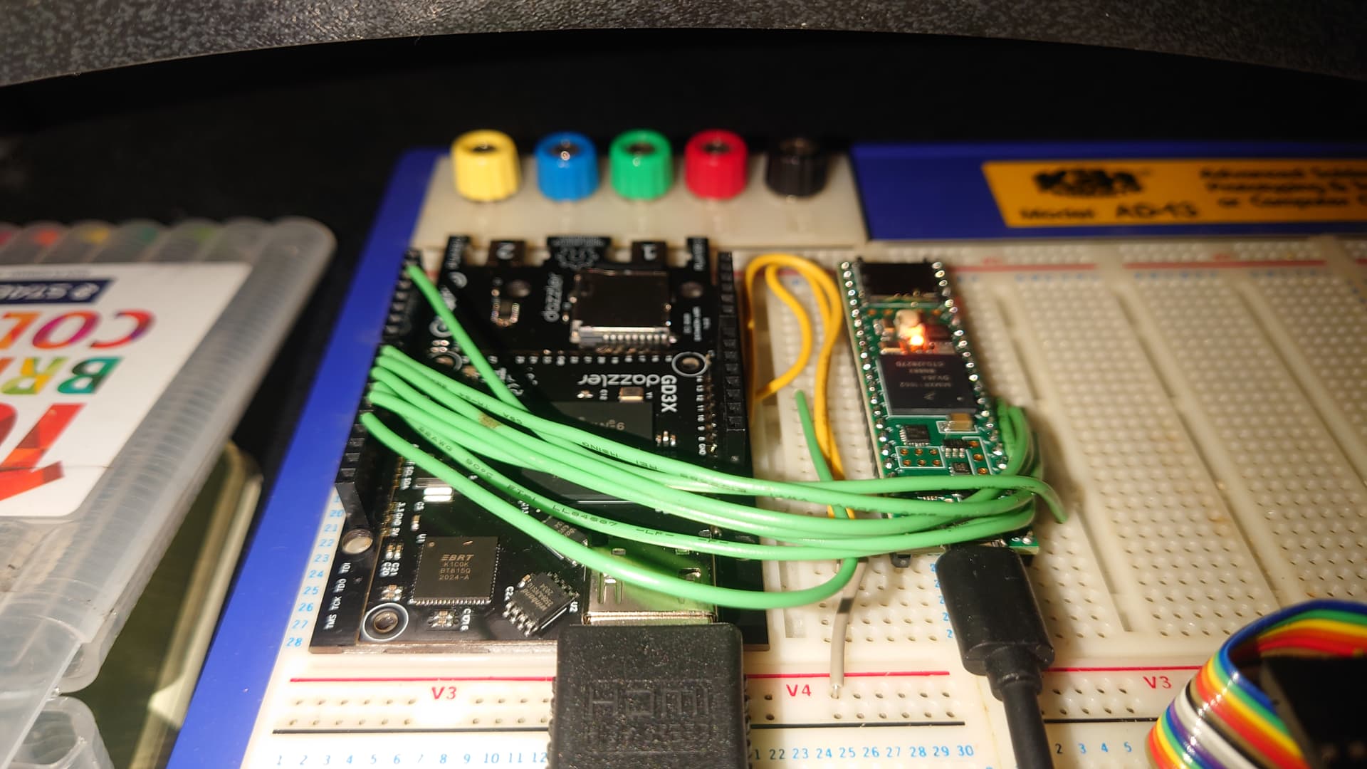
Teensy 4.1 connected to the Gameduino 3x Dazzler.

As you can see in the pictures, I am currently upgrading the CNC controller and display for seeing all the information easily and with a resolution of 720 x 1280.

This will have so many positives when it comes to machining out parts, not only speed, but also showing all aspects of the machine while it works.

The main idea behind getting this setup is so I can fit a display like this in the MGF and monitor everything about the MGF Electric Power Unit, what do you think? Could look a little Tesla’ish.

What’s the cost though? Well, here is the list: -

  1. £26.48 - Teensy 4.1 microprocessor

  2. £40 - Second hand monitor (still in the post)

  3. £43.99 - Gameduino 3x Dazzler with HDMI out

  4. Some time programming, drawing the screen, generating menus and integrating it all in the machine.

So all this full control and modern looking display system for £110.47 plus a little programming time, where basic controllers can set you back £2500 plus on a home CNC. Also, this will double as the display in the MGF :-D.

What’s the difference then between what I have at the moment? Well, the current microprocessor is an Arduino Mega 2560 and these are the differences: -

  1. Arduino has 256KB of flash (program storage) where the Teensy has 8MB

  2. Arduino has 4 serial ports where the Teensy has 8 (better for connecting to all the MGF devices)

  3. Arduinos benchmark speed is 7 where the Teensy is 2381

  4. Arduino runs at 16MHz where the Teensy runs at 600MHz (and is overclockable to love 1MHz with cooling)

  5. Teensy has a Micro SD card slot

  6. Teensy has a Real Time Clock built in (good for the MGF project also)

  7. Teensy is, well, Tiny

  8. I think the display difference is fairly self explanatory, where every time I need to make changes to a milled part I have to go through the extensive menu system with only 8 lines of text. The Gameduino allows me to create pop up windows to easily select programs and features.

As you can see this is a little extra work than I was planning, although will make all the projects even more fun and easy to use. I only received the Teensy and Gameduino on Wednesday and have already got it to start looking like a CNC display.

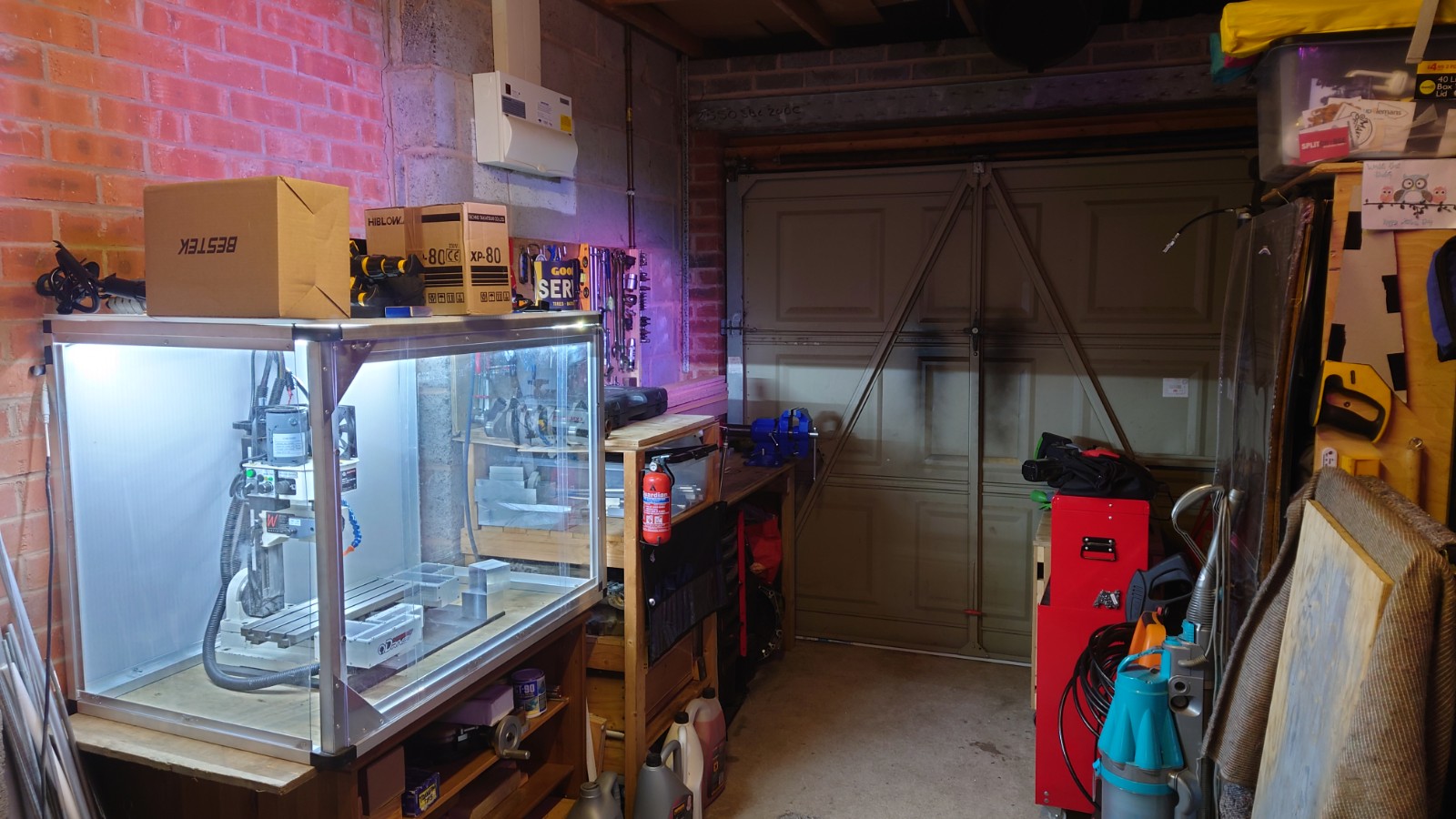
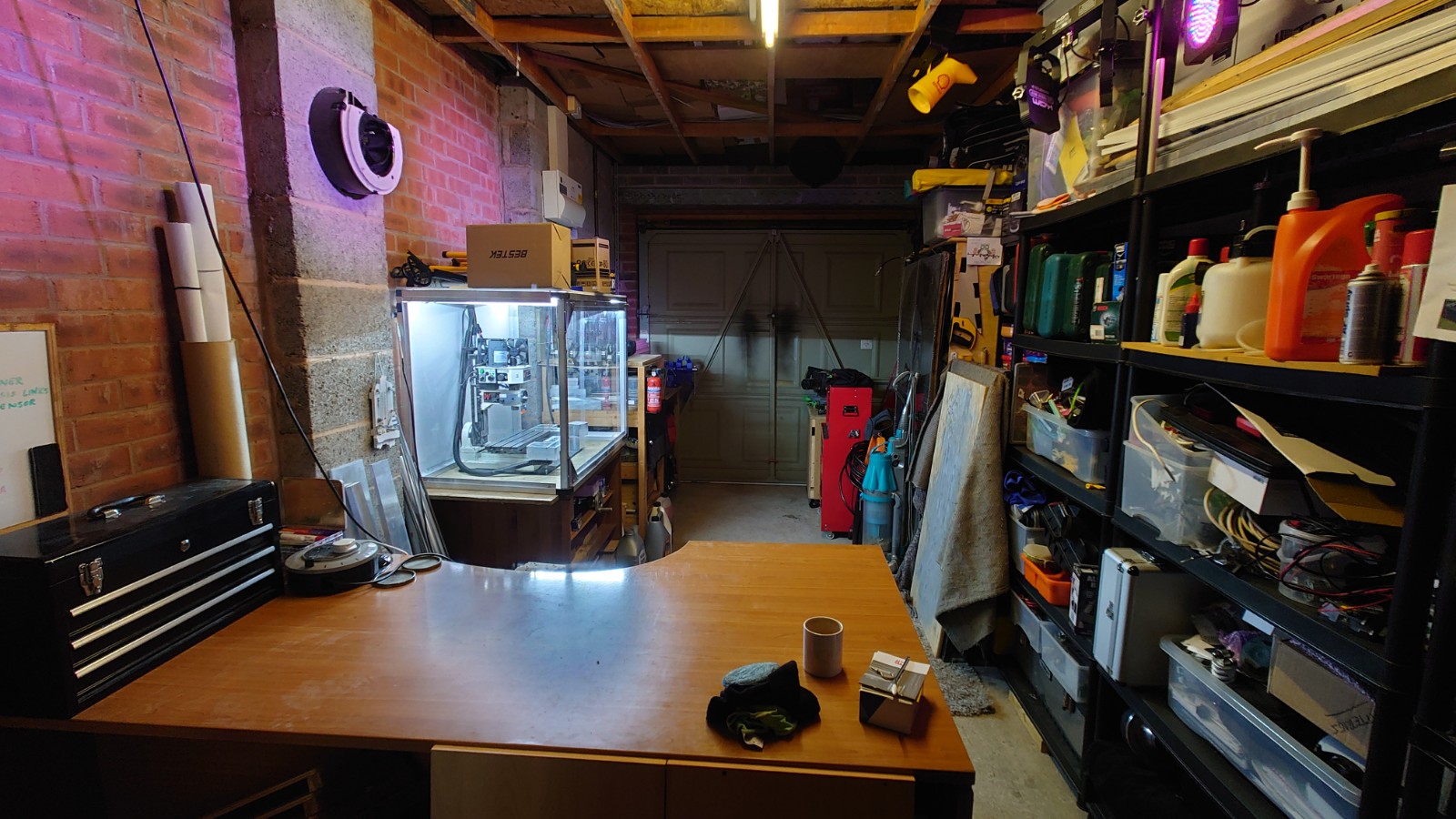
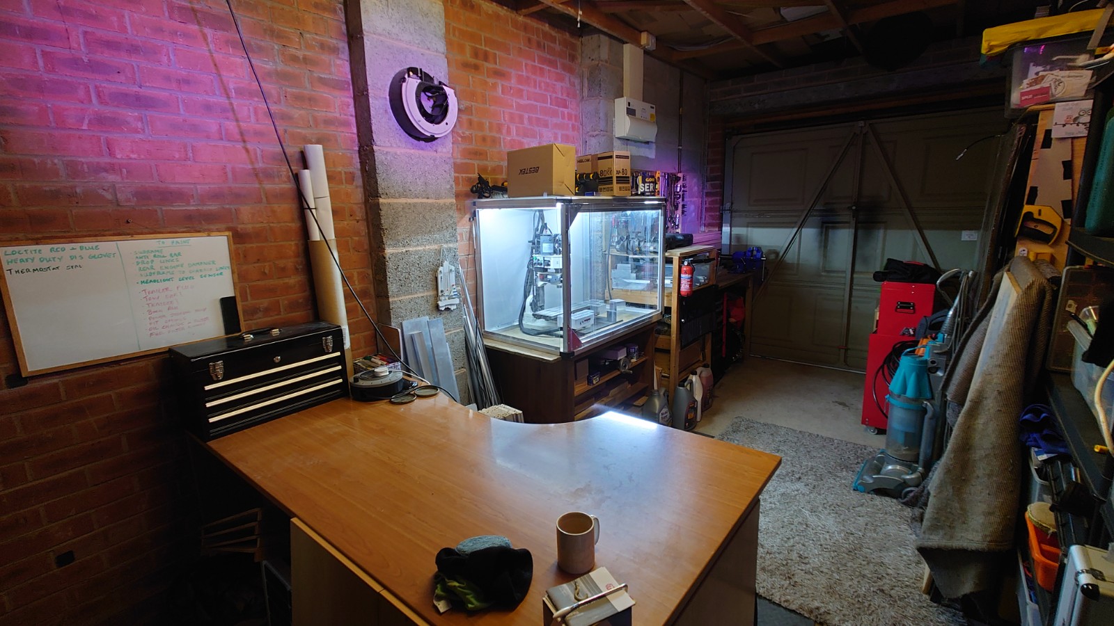
Now the Garage is sorted, the MGF has been over here and the mill is progressing nicely, I should be able to move things along so much more (all settled in now).

Has anyone else tried this type of configuration? I think it makes the machine look ultra modern.

Kind regards,

Neil.

1 Like

Good evening all,

The CNC machine is quickly becoming just that, a machine capable of accurately accepting GCode and turning it into a product with just the press of a button.

Here is the latest (well, last night) version of the program, and it is now fully married to the CNC code, so there is just one program to run everything from the GCode conversion, HDMI display picture through to the machines full movement and control.

These are the items that are now available on the new system: -

  1. Jog mode with zeroing facility - Zero X and Y Axes and shows both zeroed value and absolute machine value for each Axis.

  2. Spindle speed graphic to show the actual spindle speed (currently a pseudo value)

  3. Circle mode, to machine circles manually with all the features (internal, external, climb/conventional milling, feed speed and diameter).

  4. Axes Panel now moves with the machine, where the edges of the displayed box are the machines movement extremes, will show soft end stops also when written.

  5. I’ve fitted the white 8x8 LED matrix to it also just for machine status at the machine.

  6. Also I have now managed to streamline the code even further, where it runs through all the code in just over 5ms, that’s 200 times per second, this means I have been able to run the machine at a much faster feed speed. Last night I tested the circle program to 420 mm/min or 7mm/sec, that’s quite fast considering the machine is capable of moving me out of the way while leaning on it.

The purple board is the ISO7762F isolator chip from @Alexander_Jones that prevents earth loops from destroying the microprocessor when the ODrive pulls loadsa current. Works a treat, has no issues at all :star2::star2::star2::star2::star2:.

Sorry for the flickering display, this was recorded on my phone.

I am hoping to take the machine and some projects to the NEC in Birmingham next year too, watch this space ;-).

Here is a quick video: -

Kind regards,

Neil.

Hi Neil, Any chance of seeing the code/wiring on Github?