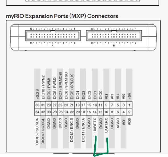
I’m trying to send the ‘odrv0.axis0.Iq_measured’ value to MyRio through UART communication.
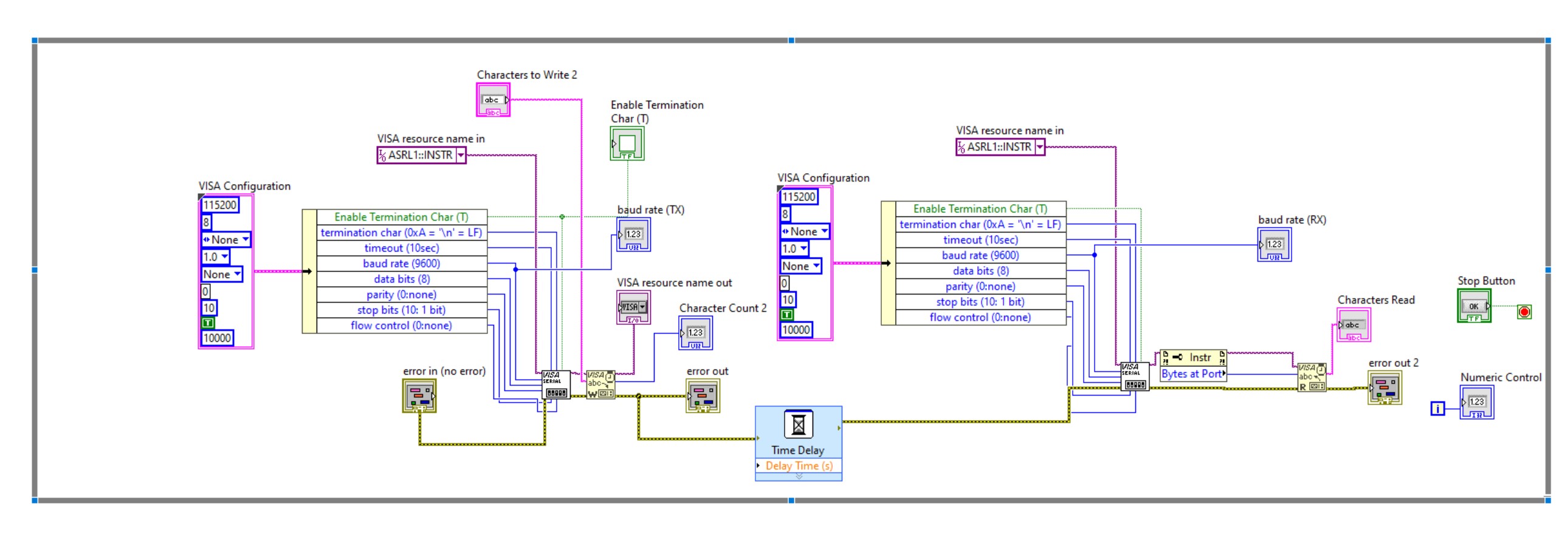
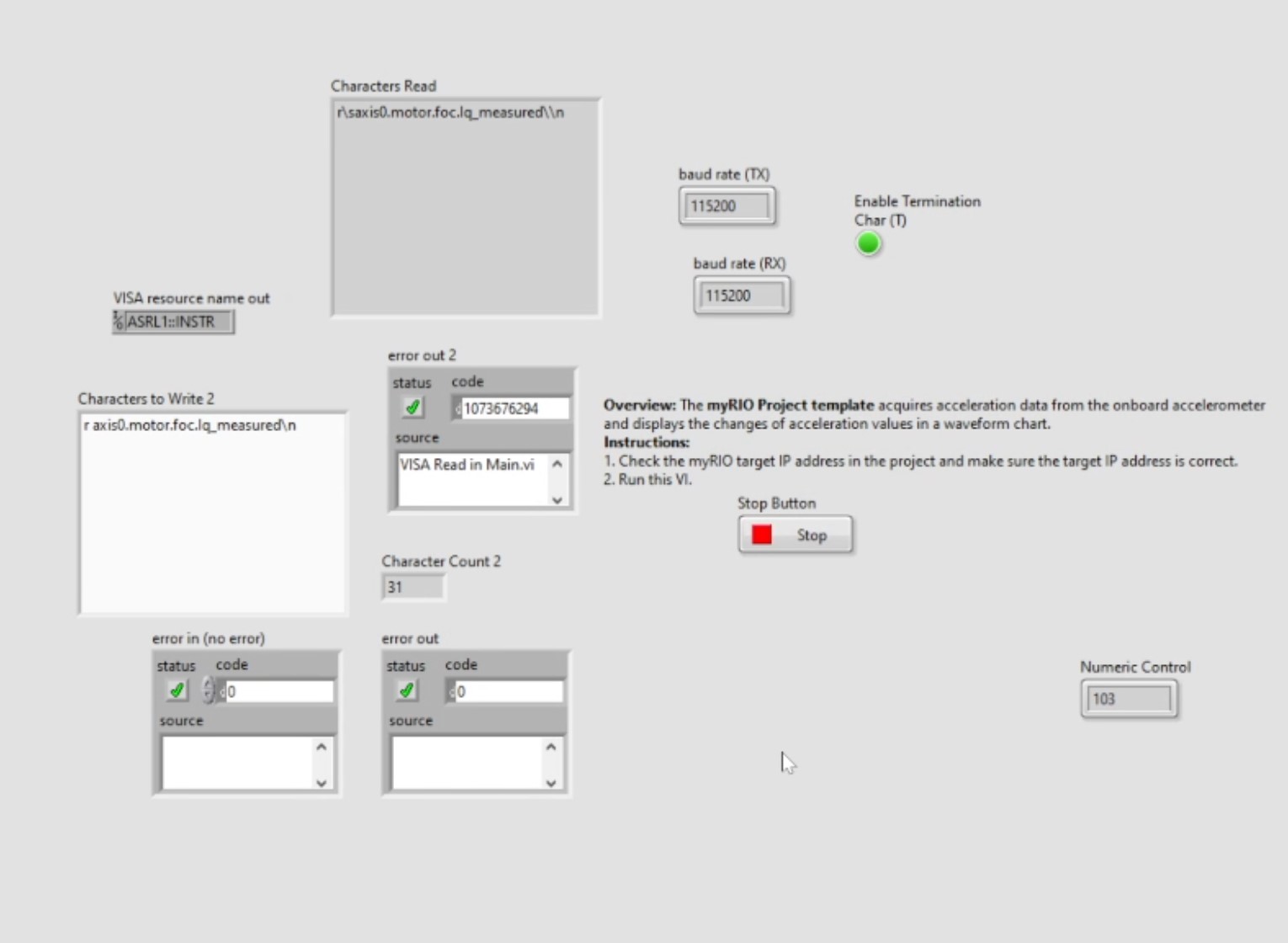
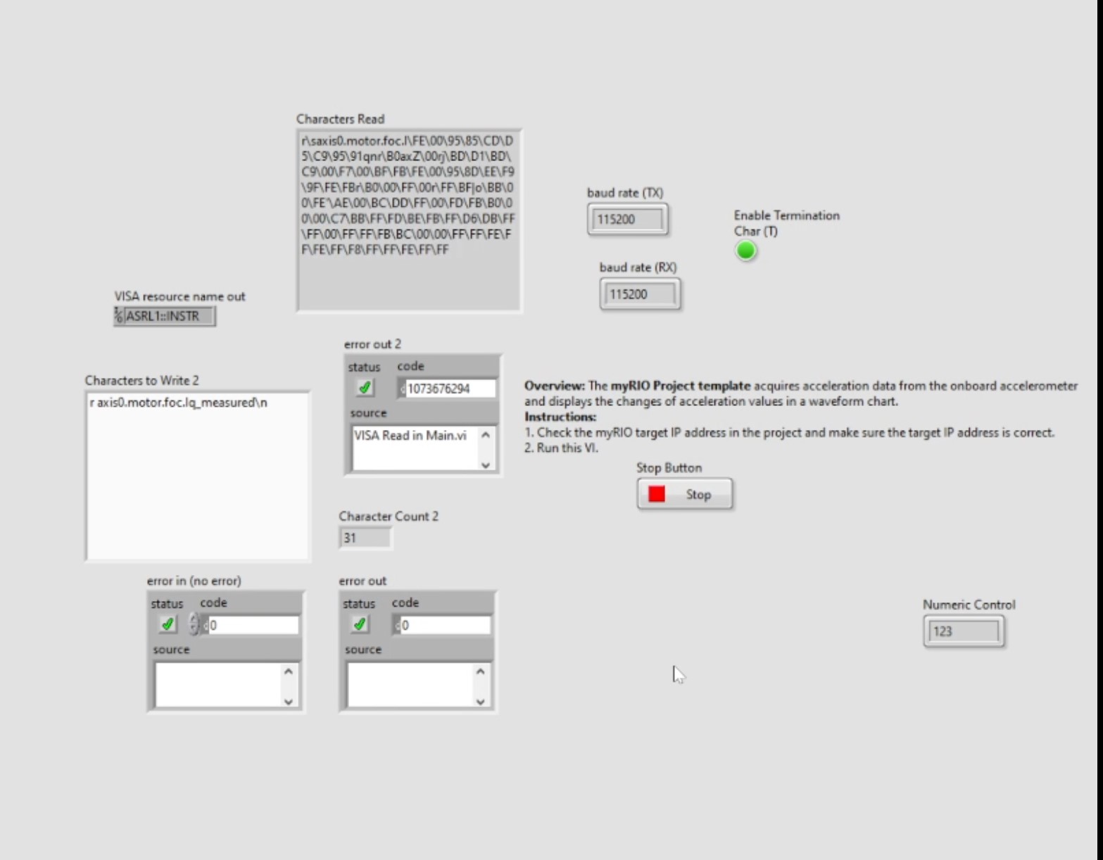
The LabVIEW block diagram is shown below and I checked it properly sends the message (r axis0.motor.foc.Iq_measured\n ) by receiving the message at RX in the same MyRio.
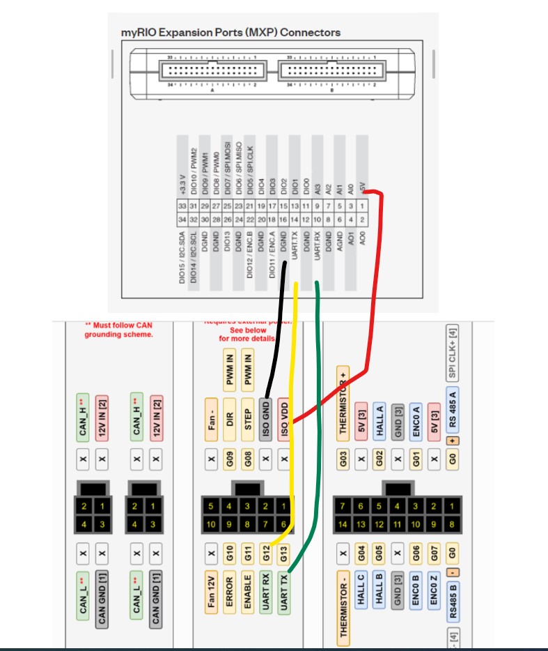
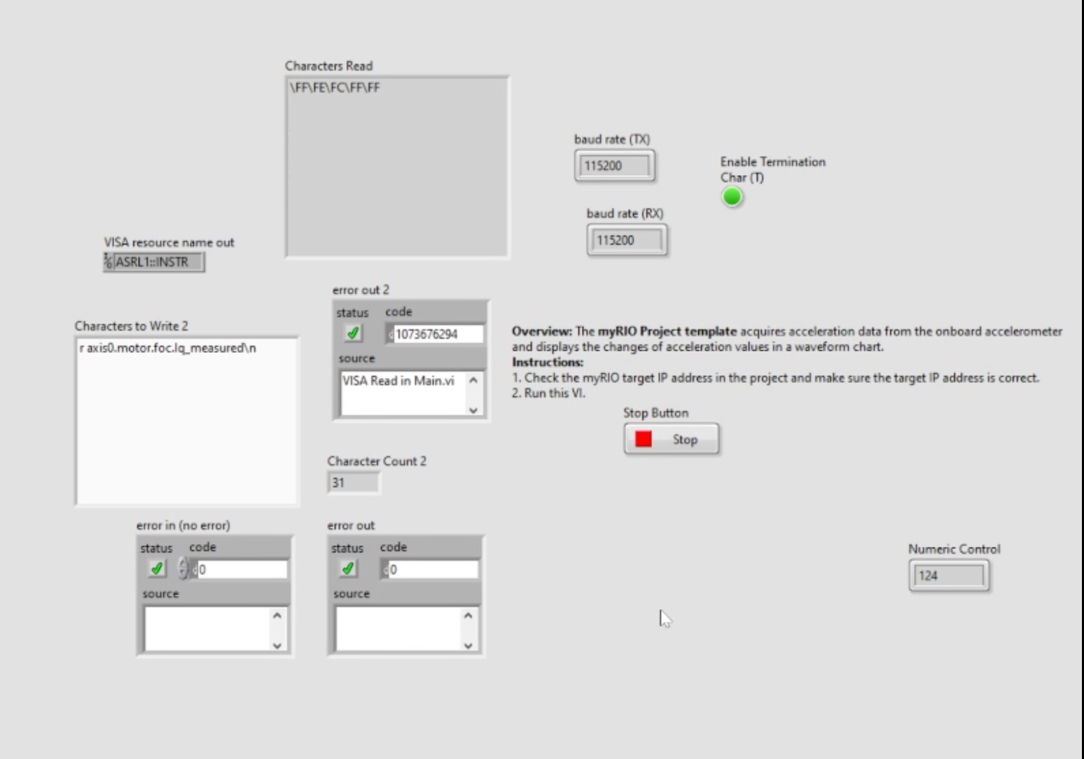
However, If I connect the VDD and ground, I don’t get any response at the MyRio’s RX port. If I disconnect the VDD and ground, I can get the very short hexadecimal values but it’s gone. (I need to delete the TX input values and put them again to get the new values)
VDD and GND should always be connected. My guess is that you’re receiving random noise when they’re not connected.
It looks like on that Labview screeenshot you posted the termination char is at 9600 baud, unless I’m misreading the configuration? Does the VISA Configuration override the baudrate? Note that the ODrive doesn’t use the VISA protocol, so you should just use raw UART communications.
Do you have a logic analyzer or similar that you can use to see the raw data the myRIO and ODrive are sending?
Thanks for your response!
I tried to check the signal through the oscilloscope and get the proper TX from Odrive.
The issue was becaise I set the position control mode as the analog input.
My motor setting code is below. (ODrive does not response from MyRIO’s TX signal)
After I changed it to the position closed loop control mode, it’s working well.
Do you know why UART does not work in Analog input position control mode?
If you have the analog endpoint mapping setup, then it’ll override the commands given over UART. I’d recommend disabling that endpoint - it’s really one or the other.
Are you able to read the iq_measured and everything correctly?
Now I tried the analog input position control setting and it’s working well.
I don’t know why the previous setting didn’t work because I tested the old code and it’s working well now.
I added the below code at the beginning of the code and I suspect that It would clear the all previous error.
I’d generally recommend against using the analog position input if you’re already using UART for feedback - you can just use UART for sending position setpoints directly, it’s much more precise. That being said, I’m glad what you have is working for you!