I’ve been having some issues with connecting to the USB ODrive v3.6 56V. Last weekend, I wired up two ODrives to a RPi, which seemed to work great. The motors were able to successfully calibrate and run to positions on command. This translated to this morning, where the project continued to exhibit the same behavior. However, this didn’t seem to persist: after attempting to connect the USB directly to a workstation, the ODrives no longer seemed to want to connect to anything – running lsusb on the RPi, a workstation, and a laptop all seemed to not detect the device whatsoever. The power light is on, the only issue seems to be the connection. All the cables were verified to work as expected.
To solve the issue, I attempted to reflash the boards with new firmware. The flashing was successful, but didn’t seem to change anything connection-wise. However, after repeated flashes and power-cycles, the one of the boards started smoking, with the USB housing melting and fusing the cable to the board. This is shown below:
I don’t know how plausible this is given the actual electrical design of the ODrive, but any time you melt a low-voltage connector like that, it implies that you’re putting a ton of current through the shield/ground of that connector unintentionally.
My guess is this: the motor ground and USB shield are probably shared on the ODrive. When you had the odrive connected to a Pi, ground and power on the pi are fully isolated due to being plugged into a wall wart, which maintains full isolation between the AC and DC sides.
When you plugged USB into a workstation, USB ground became earth ground due to the workstation shielding design.
That then interacted with however you’re powering the motor-side of the ODrive. Perhaps motor supply (-) is connected to a power supply or battery or something such that it’s actually a voltage below ground? In which case you’ve set up a loop where the motor supply is shorted through the USB connector through the chassis ground of the workstation through earth ground.
I’d go looking for some electrical loop of that sort.
Wonder if you connected the break resistor. What power is your motor?
As motor speed ramps down, it generates electricity and need to go to the resistor or else push up voltage on motor power input line or flow into unexpected path, may be?
Thanks for replying! I also suspected a ground loop initially, but the Pi and the workstation were grounded from the same 24V source, so I don’t think that’s an issue.
We are using a brake resistor. However, I don’t think the brake resistor would make any difference: The issue arose when trying to just power on the board with a USB hooked up rather than when running any motors.
This can happen if you’re not using a USB isolator, and the ODrive’s ground lead is improperly connected - effectively the ground connection is completed through the computer.
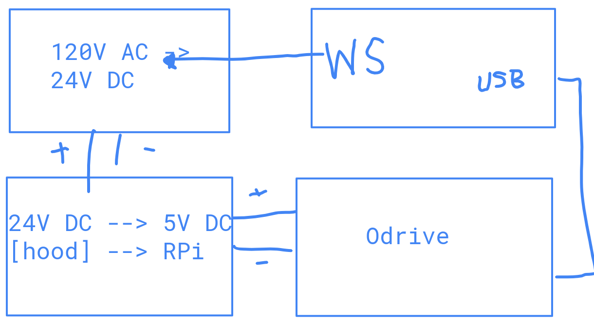
Oops! I think you’re right, the workstation was powered directly to mains – apologies, that’s a pretty big misrepresentation on my end. Think a ground loop could have been the issue, thank you! The setup likely looks exactly as you would expect; 120V AC → 24 DC → 5v to the Pi → USB connection to the Odrive, and when connected to a workstation it was just a direct connection without any sort of isolator or other protective methods. Apologies for not including a photo, as my phone isn’t on me, but I attached a wiring diagram in the post below.
I think that’s gotta be the issue then! Interesting that a ground loop would cause this behaviour though.
Looks like a ground loop! From what I could tell, the USB cable housing itself got hot enough to melt the surrounding plastic, so around there is where I’d assume the smoke came from. Here’s a wiring diagram:
Have ground loops ever burned up/bricked a board like this? Do you think the second board that isn’t responding to commands could be fixed by swapping out the chip adjacent to the USB port?
Oh yeah that’s definitely a ground loop - this is why we recommend USB isolators. Could absolutely knock out the STM32.
You could try just replacing the USB connector and seeing if that works - it’s an Amphenol 10103594-0001LF. If it’s still dead, then the STM32 is likely broken and you could try replacing it - it’s an STM32F405RGT6.
So a ground loop isn’t INTRINSICALLY bad. The issue is when you somehow create a potential accross it that you weren’t expecting.
By way of example: PC power supplies are typically floating/isolated, so both the + and - of the 12V output are high-resistance to chassis ground. Once upon a time, I modified one with screw terminals to do some high-current 12V RC motor testing, because as 12V/100A power supplies go, PC supplies are cheap and good. I was trying to figure out why I seemed to be getting -12V on the output though.
What had happened is that, when I put the screw terminals on the chassis, the 12V+ lug shorted out to chassis ground internally, so the 12V- lug ended up at 12V below earth ground.
I figured this out while I was trying to probe the output with an oscilloscope, to see if maybe there was some wild noise on the supply confusing my multimeter. The giveaway was when the scope lead lit on fire. The circuit was +12V through chassis to mains earth through scope chassis to scope negative through the negative lead to 12V-, which was at -12V instead of 0V.
So in any event, one possibility is that your 24V supply had a similar inversion, where earth GND happened to get connected to +24V, or maybe your 5V step-down happened to be inverting, where +24V was connected to the negative of the output, or maybe the issue was your motor supply voltage which doesn’t appear to be indicated in that diagram.
But anyway, that kind of direct connection to a floating supply that on its own wouldn’t be a problem is the type of connection to look for when diagnosing why a ground loop is passing enough current to melt stuff.