10 Nm torque motor selection

Hi,

Does anyone have suggestions for which of the many motors advertised from our favourite supply country would work well for attaching a 20mm dia cable drum to act as a resistance force to someone cyclically pulling on the cable?

10Nm would be max, mostly run at 2 - 4 Nm I expect.

thanks :slight_smile:

1 Like

Interesting idea. Should make for a much more portable machine than iron weights. Or stick a battery on it and you can charge it up while you work out :slight_smile:
The 10850 size would probably be good. Advertised as 15Nm max, so intermittent 10Nm should be fine without active cooling.
Hoverboard motors would probably be good too (and cheaper), but I’m not very familiar with them. Their power ratings seem to be vastly lower than quadcopter motors of similar size, but the basic design is the same, so I suspect it’s just due to lower expected speed, poor cooling, and the fact that humans will be riding on them so safety margin is much higher.

Yes exactly. “Torque motors” are rated for stall current with nothing but passive cooling, whereas quadcopter motors assume that their only load is a big cooling fan. If you tried to run a “2kW” 24V 40A quadcopter motor at 40A stall current, it would very quickly overheat.
Torque motors also have lower Kv, meaning they produce much more torque for the same current (but move more slowly for the same voltage). That makes them much more efficient for robotics applications, because resistive losses go with the square of current.

A motor like this one is NOT optimal, because it needs a huge current to produce its rated torque, and is designed to spin at thousands of RPM for its rated power.
I’d probably be looking at something like an e-Bike motor for this kind of application. They have torques around 50Nm, but will only do 200rpm or so at 48V. Hoverboard motors and other direct-drive Hub motors should be fine, too.

That said, to produce a stable torque from any motor at stall, you NEED a good high-resolution encoder, ideally an absolute encoder. (or at the very least, one with an index pulse, so that you don’t have to calibrate it on boot up). Hall sensors are NOT enough.

1 Like

No, resistive loss is theoretically the same regardless of kv. If you halve the kv, then you get 4x the resistance, which cancels out the 4x improvement from halving the current. Twice as many turns, so twice the total wire length (doubles the resistance), and half the wire diameter to fit in the same space (doubles again). There is a slight weight advantage to low kv, because the lengths of wire crossing between stator teeth are dead weight, and they’re smaller diameter with low kv. Also the wires from the battery to ESC and ESC to motor are smaller diameter.

But I did forget to account for the current capacity of ODrive. 10850 motors are available in 50kv, but even then producing 10Nm torque would need 60A, which is probably too much for ODrive’s MOSFETs to handle without active cooling.

Thanks for the input, much appreciated.

Yes, I was looking at the currents required for those drone type motors being too high. This can use a mains power supply of any volts really, so am not stuck with batteries, although they would be useful for capturing the users work done, & provide amps when needed.

The hoverboard type motors are way cheaper too, but will need a bit more mounting work.

A lot of interesting work done here on Force feedback control:

making this motor look promising: Wholesale Mige 130st For An Amazing Sound Experience - Alibaba.com

cheers :slight_smile:

But, then there’s this as well, same price:

How to choose?

Btw, don’t forget that the current through the motor is NOT the same as the current coming from the power supply, especially when the motor is stalled. The current drawn from the power supply will be MUCH lower when the motor is at low speed, perhaps lower by a factor of 10 at stall.

Can’t forget what I never knew ! :slight_smile:

The motor will be under reverse torque whilst ‘pulling’ & normal loaded torque when ‘returning’. Is reverse torque current behaviour same as stalled?, it would only be strictly stalled at the + & - peaks of each cycle.

1 Like

No, but considering the very low speeds involved, it is basically the same.

:slight_smile: But if you think about it in terms of power & energy, it has to be that way. Otherwise, the ODrive would be getting very hot indeed!
If you draw 40A from a 48V power supply, you are pulling almost 2kW, which is enough to start a fire, even with a cooling fan. (as my 1800W hot-air blower & 3-minute charcoal BBQ igniter will attest!)

A motor can be thought of as a resistor, inductor and voltage source.
From the motor’s back-emf constant ‘Kv’, you know that the voltage source only produces 1V per 100rpm (kv100). A pulley on a weight-machine doesn’t go much faster than 100rpm.
You also know that the motor’s winding resistance only produces 1V per 10A (0.1 Ohm). So your stalled motor will be running at 4V, and the moving motor will be running at 5V.
So where does the rest of the voltage go?
There is a PWM-controlled mosfet bridge (the ODrive) in between the motor and the power supply, and a mosfet has an intrinsic diode, which will recirculate some (most) of the motor current while the mosfet “switch” is in the “off” state. While the switch is “on”, the 48V from the power supply is placed across the motor. 4V is lost across its resistance (in my example), and 1V is lost (or gained) producing or sinking mechanical power from your arms.
The remaining 43V is placed across the motor’s inductance. This causes the current to rise rapidly (the higher the inductance, the slower the rise in current) and the ODrive needs to detect that and switch off the mosfet before it goes too high (in reality, with a high enough inductance and switching frequency, there is only a very small ‘ripple’ in current between PWM cycles)
An inductor is an efficient energy store, somewhat analogous to a mechanical inertia. So when the switch is ‘off’, it returns its stored energy by forcing the current past the mosfet’s intrinsic diode, and the current drops slowly until the next ‘on’ cycle.

The current from the power supply is the current in the motor multiplied by the PWM duty cycle %.
When the motor is moving slowly, there is very little voltage from the back-EMF of the motor, so the PWM duty cycle can be very low. When it is moving at its max speed (supply voltage * motor Kv) then duty cycle will be 100%. In that case only, is when the current is the same.

This is also why a low-Kv motor is useful. The mosfet bridge has 1.4V worth of diode drop (i.e. 1.4 watts per motor Amp are lost in the mosfets during the off-cycle, in addition to the power lost in the resistance of the mosfets themselves). If you can generate a reasonably high voltage in the motor’s EMF at your design rpm, then you have more voltage doing useful work, and less lost in the resistance and diode drop of the mosfets.

1 Like

Thanks for that great explanation!

Did a quick estimation of worst case to allow for:
say a bar raised from floor to overhead in an explosive move
call it 3m total in 1 second.
With a 2cm dia cable drum I get the attached approximation of around 3,000 rpm during the move
Capture

Does this mean I must consider higher speed motors than I was originally thinking?

Cheers, I really appreciate you sharing your knowledge here :slight_smile:

Hi Max,

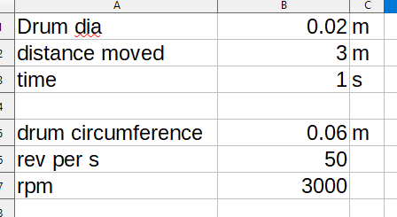
That’s a very small drum. Are you sure it’s 2cm diameter? How many layers of rope does it have when fully coiled?
For the force you need, are you saying that you need 10 Nm at 1cm i.e. you need 1000N (100kg) force?

But in any case, if the motor needs to move at 3000rpm, that’s 30V back-EMF with a kv100 motor. So you will need the 56V ODrive, but it will be fine.
Even if you had a lower Kv (i.e. high EMF) motor, or less than 30 power supply volts, the effect would be to force the ODrive to dump some power into the battery and/or brake resistor when the motor’s EMF is higher than the supply voltage. Because of this current, the motor would produce some extra resistance torque at the highest speed, and it would force you to take slightly longer than 1s to lift the bar.

The tricky part is finding a motor that can produce enough torque, doesn’t produce much more than 60V back-EMF at 3krpm, and is cheap.
That “mige” servo motor is no good, because it’s back-EMF constant is much too high. 140V/krpm means 420V at 3000rpm (Kv = 7, to put it into hobbyist terms). It’s designed for 220V applications, but it can’t actually reach 3000rpm even with a 220V supply.
Also, you don’t want to be driving a motor close to its max current / torque, because it will be extremely inefficient. Remember that torque scales linearly with current, but the cost in Watts due to resistive losses go with the square. The winding resistance also increases slightly as the motor heats up. Normally industrial servomotors have a “peak” current or torque rating about 2-5 times higher than their continuous rating. A ‘hobby’ motor usually only quotes the peak rating.

Does it have to be direct-drive, or can you use some mechanical reduction such as a toothed belt? If you can have some gearing, then a smaller version of the one suggested by dekutree earlier might be ideal. Or, if cost is less of an issue, there are companies like t-motor who will sell you a 10Nm planetary-geared actuator for about US$500.

If it does have to be direct-drive, if it weren’t for the issue of how to fit a proper encoder, I still think e-bike motors would be your best bet. With a 50Nm motor you could use a larger diameter spool, which I think would make things easier for you mechanically.

Or on the subject of e-bike motors, perhaps a ‘mid-drive’ e-bike motor might be a good one? These are designed to mount to the chain sprocket, and have a huge torque capacity via a gearbox. It’s also probably much easier to mount a proper encoder to one of these than a hub motor, i’d guess…

2 Likes

Hmm, maybe 50kv 10850 is best after all. 1000N at 3m/s is 3kW, which is 50V * 60A, i.e. you can’t really avoid going that high on the current while staying within ODrive’s voltage limit as well. And with active cooling, it should be fine. Possibly even passive cooling with a big enough heatsink. If the frame of the machine is made of aluminum, then you could use that as a large heat reservoir/radiator. Put some thermal adhesive on the transistors and stick the ODrive straight to a flat spot on the frame :slight_smile:

1 Like

In my experience, even the stock heatsinks are good enough at 60A, and it wouldn’t even be doing that near 100% of the time - presumably the duty-cycle for producing 1000N is pretty limited, by Max’s own capacity :wink:

Hi :slight_smile:

Ikr, it’s as if Physics does not want this to be simple huh.

1000N? - yes, gym weight stacks go to 100kg total of plates

Use of gearing / pulleys I hope to avoid to minimise the ‘un - weight - like’ effects of rotational inertia.

Yes the 1000N would just be peak, I’m thinking of halving that to get something working.

How about the regen braking feature…? Isn’t the motor acting as a brake during the PULL part of the stroke - is the regen resistance able to be variable to control the braking effect?
or have I confused myself

some interesting items at this uumotor site:

In the part of the stroke when you lift the bar, the motor is producing torque against the direction of motion, so it is in regen. However, it still has to put the same current through the windings in order to set up the magnetic field to produce that torque, and in my example above, the energy required to sustain that current against the winding resistance was quite high, and it swamped out the energy you get back from regen by a factor of 4.

Also, in the part of the stroke where you return the bar, the motor is still producing the same torque, but in the same direction of motion. This means there is no net energy input from regen. In a normal weights machine, do the weights get hot? No, they don’t. :stuck_out_tongue:

However, if you were to program the ODrive to apply a lower torque on the return stroke (like the spring/ratchet/resistance on a rowing machine, perhaps) then there would be a net energy input from you to the ODrive. But it would take some careful motor selection to optimise that.

Yes I saw that site earlier… This motor is still a bit too high-EMF for you to reach 3000RPM though. It’s rated speed is 500rpm at 24V, which means it could probably reach 1000rpm at 48V. But remember, with no headroom, it will have almost zero torque left at that voltage.
Also, this motor is rated to 600W, which tells you something.

How about:
http://www.qs-motor.com/product/qs-motor-3000w-70h-138-70h-bldc-mid-drive-motor-with-pulley-for-timing-belt/
(aliexpress)

From what I can tell, its “continuous current rating” is 40A (3000W/72V), it can be overloaded for “long” periods to 80A and for short periods to 120A. Absolute maximum “peak” current is 180A.
Probably, that’s also where they get the 60Nm torque from. So continuous torque rating at 40A is probably 13Nm which is still plenty enough.
It produces 72V back-EMF at 4000rpm, meaning at 3000rpm it produces 54V. It should just about be possible to do your ‘explosive move’ without risking damage to the ODrive.

Another problem I just remembered is that ODrive’s PWM duty is limited to I think 70%, for some reason to do with current limiting. So the effective voltage limit is 39V, not 56. I can’t find anything in the documentation about it, but I remember it being mentioned on the forum here. I’ll see if I can find the post again.

EDIT: Nope, can’t find it. Only this mention that it can usually get to 75% speed How to get the maximum speed?

Hi & thanks, I see what you mean by regen not helping.

On the uumotor, or it’s bigger brother, the extra torque available would allow a bigger drum & smaller max rpm; if I manage my expectations low enough, it’s 40Nm max means potential 8cm drum dia & 1/4 the max rpm.

The back EMF would be the same magnitude whatever the motor torque was set to right? As in somebody throwing a 5kg simulated weight up & down would create the same back EMF as an 80kg ‘weight’ if the same rpm is created.

‘Tonal’ have something similar working:

Correct, modulation magnitude of the PWM is limited to 80%. That means you can never go above what would be 80% throttle on an ESC. I think the reason for this is to always allow for some control headroom.
The ODrive is designed as a motion controller for robotics, not a powertrain drive. Most industrial servo drives will also trip out on error, or at least give a warning, if the modulation goes above 80% or so, as it normally indicates control instability.

However, the modulation magnitude limit is not an issue for back-driving, i.e. the motor acting as a load. It could perhaps limit the regen torque at high speeds, maybe? But it won’t fundamentally limit the speed that you can back-drive the motor, not until the EMF goes above the power supply voltage.

Yes, the EMF is a function of rotational velocity, it is independent of torque.

Thanks for the help & sorry for my late update.

Been studying up on motor types & their differences, it is looking very much like hoverboard motors are the go:
the back EMF’s are very low
they have been working on boards that sit at O or near RPM with loads of torque to balance the rider
there’s a few around cheap from pple selling used boards :slight_smile:

I also appreciate the comment about Odrive design for robotics applications- positional move accuracy etc - where all I really need to do is have the motor provide a settable torque without any other feature. Some position info can be taken from a pulley on the operator side later.

I also wonder: would a simple brushed DC motor do the job with basic current control? or would the brushes cause sparking etc problems when rotation is forced backwards against applied electrical power?

Thanks again !

Hi Max,

No, brushed DC motors are really terrible for torque efficiency and torque ripple. Since the coils are on the rotor, cooling is extremely difficult, especially at stall. And because of the mechanical commutator, torque ripple is very sharp, and they are only able to energise one of their many coils at once. (most brushed DC motors have “one pole pair”.

ODrive + radial-flux PMSM (aka a standard brushless DC motor) is probably the best solution for this. Because ODrive can make use of a high-resolution encoder for commutation, it means that its torque ripple is much lower, and torque efficiency significantly higher, than other drives e.g. those using Hall sensors. Using such an encoder, it is also capable of applying cogging compensation in software, which will reduce torque ripple effects dramatically. But cogging compensation does require an extremely high resolution encoder, especially for high pole-count motors.

The encoder is really key to getting precise torque output from a brushed DC motor, because it’s not just about which coils are energised (as with simple Hall sensor control) but by how much each coil; is energised, to ensure that the field between the coils and the magnets is always tangential as much as possible, providing optimal torque output which is linearly proportional to current. Look up ‘Field-Oriented Control’ - this is the control scheme used by ODrive.
The higher resolution the encoder, the closer you can get to a perfect torque transducer. Especially where cogging compensation is involved.

I’d be willing to bet that these boards are not using Hall sensors exclusively for feedback. They will have an additional encoder to get that precise torque control.

Oh and whatever you do, don’t put your encoder on a belt or gearbox. :man_facepalming: