Teardown time!
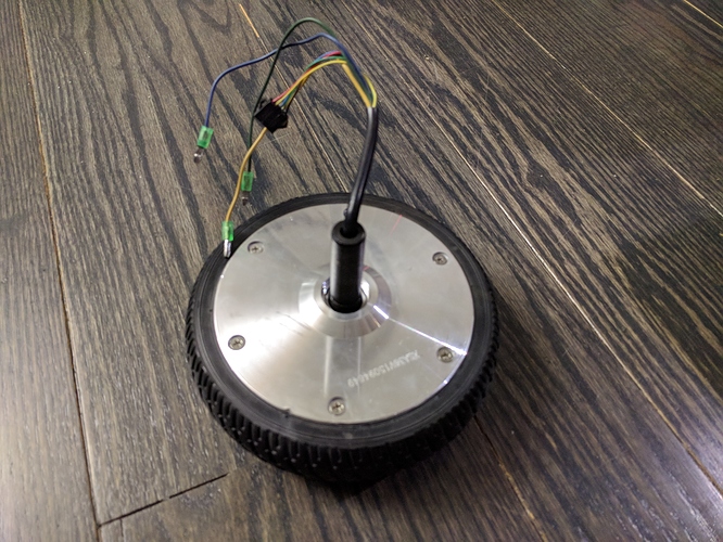
Here we have our specimen, a new hoverboard motor.
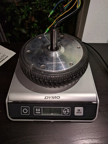
First thing I noticed is that it’s really heavy. Specifically, it’s 3146g heavy.
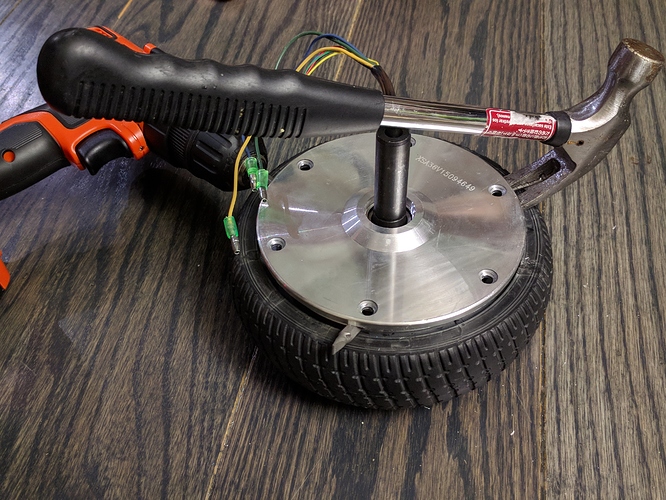
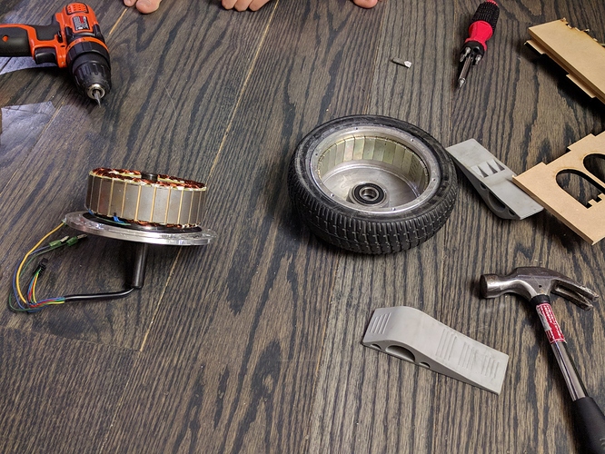
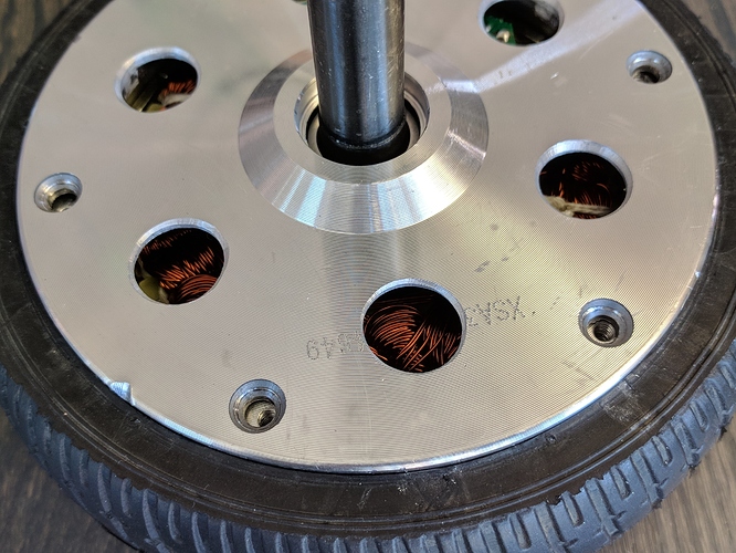
Next, let’s crack it open. There is a bearing between the aluminium plate I’m trying to get off and the shaft. This is press-fitted. I think on some models you can easily pull the cover off, but it was pressed on hard in my case and would not come off by pulling.
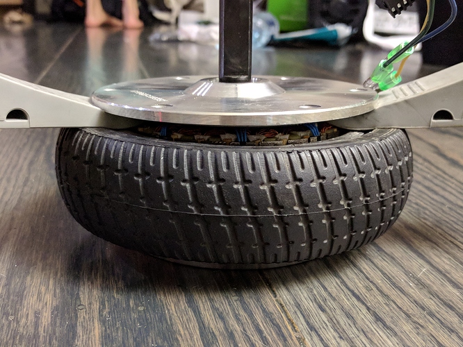
Yes those are door stoppers… You can see the stator starting to peek up there. Since my motor would not separate at the shaft-to-plate interface, I had to pull the stator out of the rotor, and therefore fight against the strength of very very strong neodymium magnets. If you try this yourself, I warn you, the pinch risk is real and terrifying.
After some thorough convincing by the hammer crowbar end, a flat head screwdriver and peices of wood as levers and spacers, I managed to get the stator out.
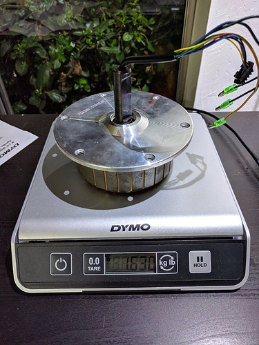
Stator and cover plate together weigh 1630g. From weighing the whole thing before, we know the rotor weighs 1516g.
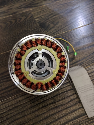
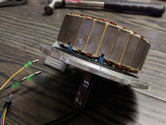
Photo of stator.
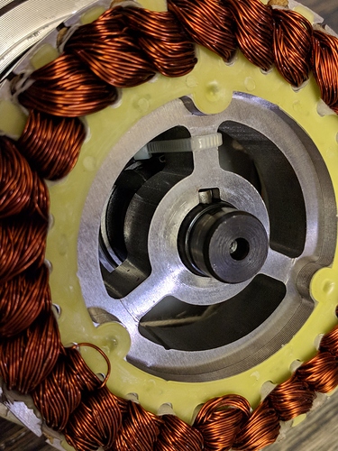
Another photo of stator.
More photo of stator. Here we can see the hall effect sensors used to do the 120-degrees block commutation as is customary for very basic brushless controllers. The stator has 27 slots/teeth/coils.
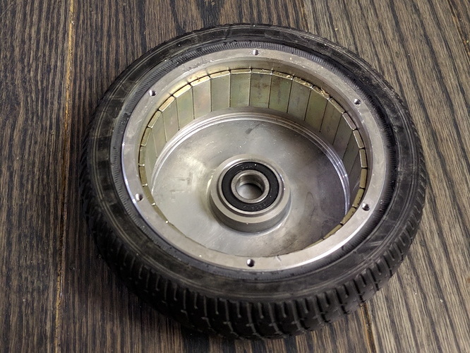
Here is the rotor. We count 30 magnets, so it’s a 30 pole machine.
So we have a 27 slot 30 pole machine, aka 27N30P. Above is the analysis of this configuration by the Emetor Winding Calculator. Each phase is wound in alternate polarity around three consecutive teeth, then the next phase is, and so on, as per the diagram. One interesting thing to note is that this motor is equivalent to a 9N10P motor repeated 3 times.
Measurements
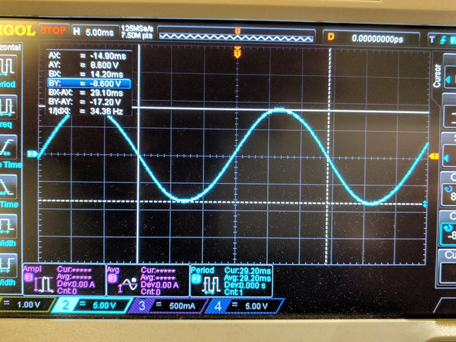
I did the drill test, and got the above trace. First thing to note is that the back-emf is very nicely sinusoidal, I’m starting to like these motors. The trace shows 17.2V peak-to-peak, and 34.36Hz.
Let’s calculate the kv rating of the motor.
Hobby motor kv ratings are measured in RPM/V. However, this is actually a little ambigous: what votage are we talking about? Specifically it is peak line-to-line voltage (aka phase-to-phase voltage). The scope probe was on one phase, and the scope ground was on the other, so what we just measured was exactly this voltage, which is great. So the peak voltage is 8.6V, half of the peak-to-peak voltage.
We know that the electrical frequency was 34.36Hz. We know that the electrical frequency is 15 times faster than the mechanical rotation speed, since we have 15 pole pairs (30 pole motor). So the mechanical rotation was 2.29 rotations per second, or 137.4 RPM.
We simply divide the speed by the voltage to get the kv value: 137.4 RPM / 8.6 V = 15.98 RPM / V.
That is extremely low compared to most hobby aircraft brushless motors, even the big ones have kv values in the 100 RPM/V range.
The next thing to test is the phase resistance. I don’t have a picture of this, but the setup is basically to connect a bench power supply across one phase and another phase. I set the supply to current limit to 4A and it put the voltage at 1.36V. Assuming a wye connected motor, each phase only drops half of the voltage, so 680mV each. This gives a phase resistance of 680mV / 4A = 170 milli-ohms.

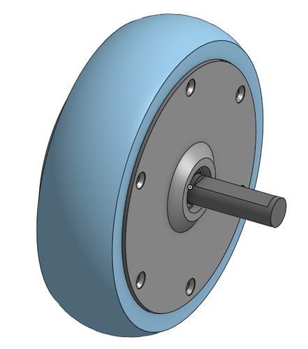
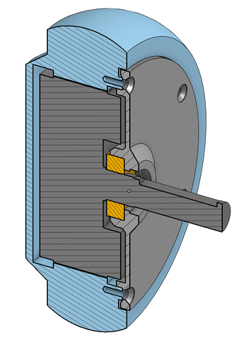
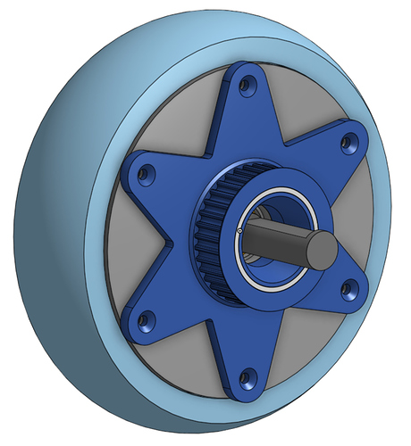
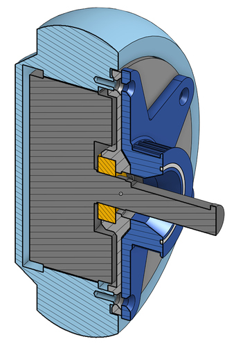
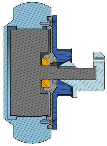
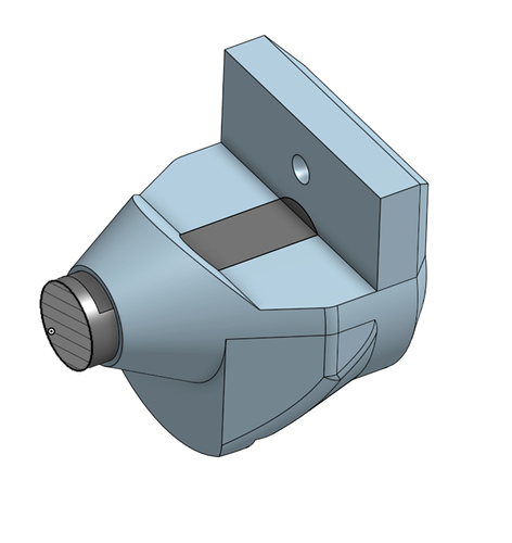
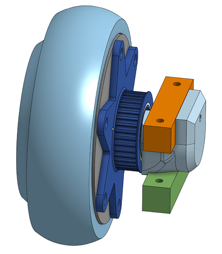
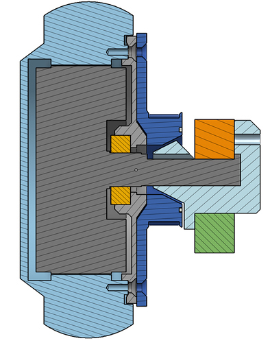
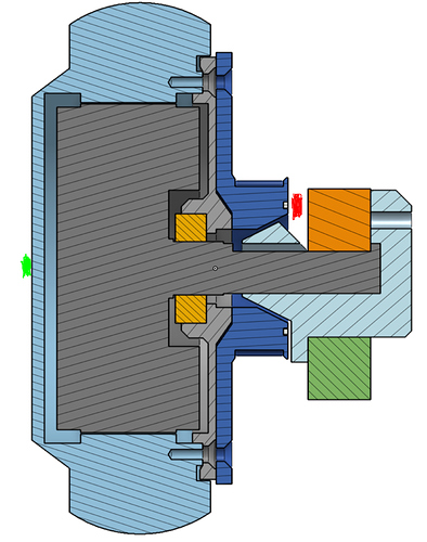

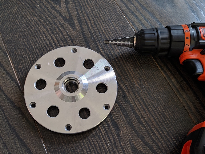
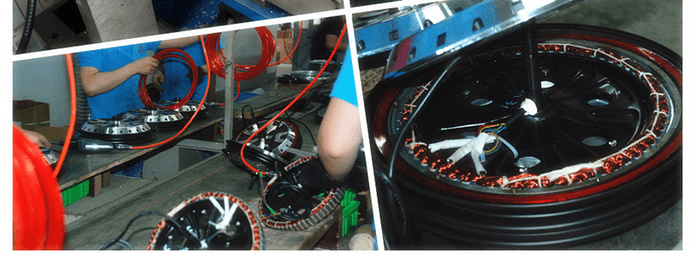
 They cant get the hole spacing right in the specs, and the pictures vary within the same product… Most gimbals motors I’ve bought from them didn’t match either the pictures or the specs. Luckily, I was 3D printing/Laser cutting the mounts and the hole size and spacing was arbitrary.