Current sensing resistor for low current motors

Hello Everybody!

I have just received 3 odrives and can not wait to get everything up and running.
The encoders are still in transit so, for now, I want to test out sensor-less mode.

My goal is to run 4 motors, position controlled simultaneously.

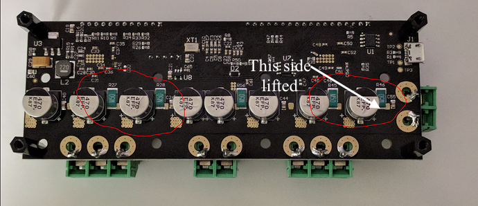
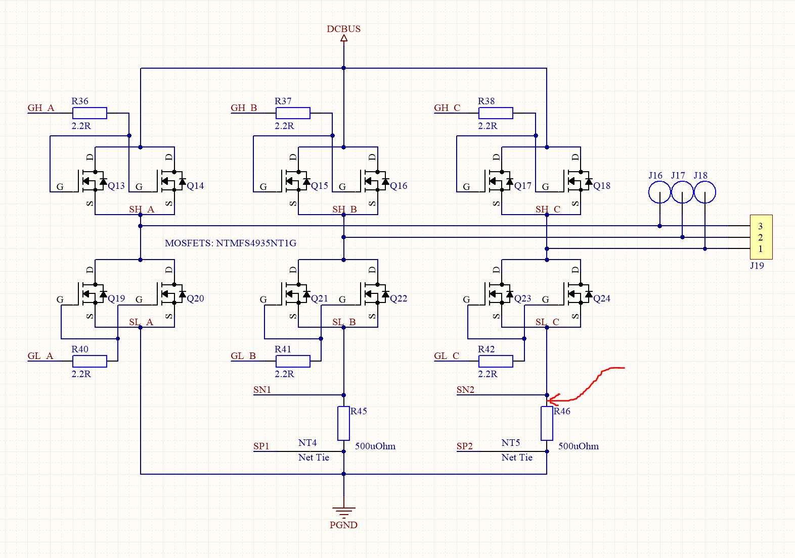
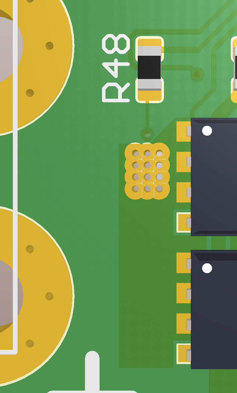
I have been in contact with Oskar before my purchase and he suggested that I changed the current sensing resistors due to the low current draw of my motors

Can someone tell me which resistor I would need to change and what would be an appropriate value for these motors?

Met vriendelijke groet,
Bastiaan

So here is how I would calculate it:

  1. Start by taking the max current range that you require. Something like 2x the peak rated current of your motor (to give some headroom) is a good choice. Let’s call this I_range.
  2. Look at how motor->current_control.max_allowed_current is calculated in low_level.c. You want this to be to equal I_range, or the nearest possible larger value (possible values depend on available shunt resistor values).
  3. For low currents, like your case, use local_regs->Ctrl_Reg_2.GAIN = DRV8301_ShuntAmpGain_10VpV;
  4. You can trace the code backwards from motor->current_control.max_allowed_current to check what value of SHUNT_RESISTANCE you will need.
  5. Select a suitable resistor. I recommend this series.

Feel free to let me know what value you came up with, and I can check that it makes sense.

Cheers.

1 Like

Thanks for the reply,

  • the peak current of this motor is 1.5 A. --> I_range = 3 A
  • With Ctrl_Reg_2.GAIN set to ShuntAmpGain _10VpV, the max_swing value would be the max allowed current.
  • The shunt conductance should be 20.8883. Shunt_Resistance: about 50 mOhms

Another question:
Could I allready test my motors without these resistors in sensorsless mode without harming them?

Yes, with 50 mOhms I calculate it to 3.2A, perfect.

I would not recommend running the motor until you have replaced the resistors. Also, note that you should only replace these resistors (not the middle one):

You also need to change a bunch of parameters due to low current and high resistance of your motor. The following are a good place to start, but you will need to tune it:

.vel_gain = 1.0f / 10000.0f,  // [A/(counts/s)]
.vel_integrator_gain = 0.0f / 10000.0f,  // [A/(counts/s * s)]
.calibration_current = 0.5f, // [A]
.current_control.current_lim = 0.6f, // [A]

EDIT: For people reading this now, the changes below are no longer appropriate, instad set .resistance_calib_max_voltage to 5.0f.


There is also a section of code around line 800 in low_level.c that looks like this:

    if (!measure_phase_resistance(motor, motor->calibration_current, 1.0f))
        return false;
    if (!measure_phase_inductance(motor, -1.0f, 1.0f))
        return false;

You should change the 3 places that say 1.0f to 5.0f (and -5.0f where it says -1.0f).

With some effort, I have been able to replace all 4 resistors.

I can read all settings I have flashed through USB (python) and also communicate with the ODrive with UART (Arduino). So it is flashed and it also powers on and communicates.

A single motor is now connected together with a 25 mm/ 500 ppr encoder.

If I turn the motor manually the observer state (pll_pos) does not change and also trying to move the motor with motor0.set_pos = 1000 does not work on both channels.

Did I fry the ODrive trying to desolder the shunt resistors? Or have I missed enabling some setting in the low_level.c?

I’m using a Voltcraft powersupply. In my last attempt this night I have quickly connected an Arduino to see if the raspberry pi didn’t play nice with the ODdrive, however, obtained the same results. If I open the serial monitor, with the Arduino test file uploaded to the board, I also read 0 bus voltage.

Where should I start with troubleshooting?

I think I’ve got it figured out. The motor error nummer is 3 —> phase resistance out of range.
Phase to phase is 11.6 Ohms. I’ll continue tomorrow to see what values need to be changed.

If someone has a suggestion let me know!

mvg,
Bastiaan

EDIT:

if (fabs(test_voltage) == fabs(max_voltage) || R < 0.01f || R > 1.0f) {
    motor->error = ERROR_PHASE_RESISTANCE_OUT_OF_RANGE;
    return false;

I think a maximum hardcoded maximum resistance value of 1 Ohm is bugging me

EDIT 2:

phase resistance was also out of range. IT WORKS!!!

  • next up --> after calibration it is vibrating so need to tune pid values
1 Like

Awesome! Glad you got it working! ;D

Motor0 is working, Motor 1 not so much. I think I have damaged the solder pad of R46. The copper pad lifted when i pulled the resistor. See the attached picture for which side I mean.

Is this side connected to ground? If so I might solder a small wire to a ground connection somewhere else.

1f9a3555ff13b570446d12162ce272dd0f719d2d_1_690x298

Ah that’s unfortunate.
Hm sorry but you got unlucky, that bottom pad is the other side, it’s this node:

Here you can see im more detail what is going on there:

The net is labeled SL_C_3, and goes from the pad of the power resistor to the other side to connect to the transistors and R48.

Here is a 3d view from the other side:

You may be able to solder a fix-wire between the resistor and the transistors and R48, that you can send through one of the mounting holes to the other side.

So I tested just tested my other Odrive,

Both motors are recognized and i’m able to control them.
However the motor connected to motor1 has twice the measured phase resistance and inductance compared to motor0.
Motor0 has the correct measured phase resistance and inductance. What could be the issue?
Thanks in advance

That probably means that one of the shunt resistors aren’t connected on motor 1 (i.e. no current is flowing in either Phase B or phase C).

I’ve tested the connections and also measured the resistance from ground to the positive side of R48 and R43. Everything seems to be connected properly. Is there a software setting that i could have missed that is not shared between m0 and m1?

Hm it may be related to this issue: 2 different ODrives v3.4 with different motors give phase inductance out of range on devel branch.
I will investigate.

A post was merged into an existing topic: 2 different ODrives v3.4 with different motors give phase inductance out of range on devel branch

@Bastiaan_Leonard Were you using the devel branch? If so, can you try pulling and trying now? Specifically, I just made this change:

Did not work unfortunately. The change you have made in the devel branche was already present in the master branch.

Are you available for a google hangouts and you can show me the board and how you fixed it in more detail. Let me know what your availability is like, feel free to DM me.

Was this issue eventually solved?