Hi all,
Now I want to tell you something about my project. Inspired from many others in the xsimulator community I decide to build my own simulator rig. But all of the samples are build with DC motors and expensive motor drivers. That’s not what I want to use. One of my hoobies is flying rc planes and therefore I prefer to use brushless motors.
After some invesigation in the net, I found ODrive and I start to build my own rig.
Yes I too am waiting for my ODrive and Motors (on backorder) to pursue a similar result, with 4 actuators belt geared down 5:1 Ball screw 20:05.
Your setup looks professional, but mine will be a little rough looking just for the test process.
With the build process with Rig and all parts I’ve no concerns; however its the code that’s been bugging me, I hope the code deliberation is easier for you.
thank you. Seems we have the same goal.
I’m using simtools. Have a look to this: ASCII commands makes ODrive unreachable
Hopefully I can have a look to the code this week and try to find a solution for that issue.
Greetings / Zennix
Hi Jerry,
I killed one ballscrew nut by making a video. So I have to build the second actuator first and waiting for two new ball screws.
The response of the motor with signals from simtools is working so far. Tests are pending.
I tried to implement the end switch to the software. But no luck till now. I think that feature is very important because I saw the balls screw nut running with full speed into the hard stop only with a 150W power supply. Don`t know what happend with the final 1000W supply.
Hi,
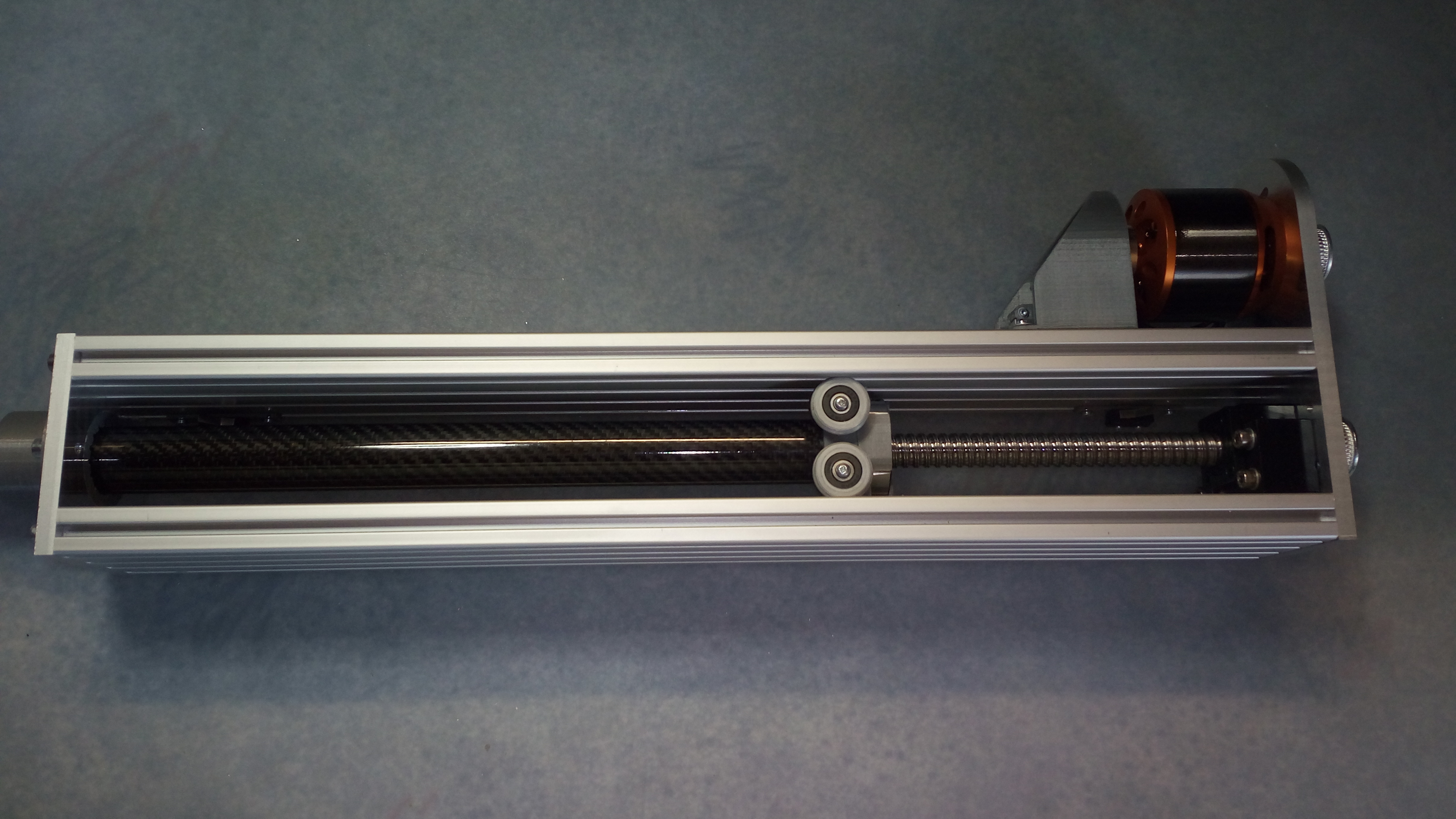
here is a little video to my progress. It shows the actuator moving by simtools. Normally the way of of the actuator is from 0 to 700.000. In this test simtools only uses max 65.000, the velocity is also limtited to 150.000 of 650.000, because my powersupply.
I have the 20.05 ball screws and 1200w*48v PSU’s, waiting on carbon fibre, and the thing that is taking the longest, it M2.5/3/4, I think they must have been lost
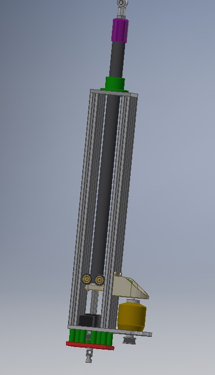
At the moment I’m going blind trying (operative word trying)to produce CAD parts, but the motor mounts work enough for the test, and if all goes well “Aluminium and Carbon Fibre”
but that’s a way off.
I’m making exactly the same thing as you are, what type of pulley are you using? I’m using sfu2005 what are you using? I will post it on here when mine is done.
Why aren’t you using a linear bearing on the top?
How much force does it have?
What voltage are you using
What is the gearing ratio?
What motor are you using? (diameter? length? link?)
the power supplys has both 40Amps so it shouldn’t be a problem.
My tests without load are working with 30Volts and less than 3 Amps.
In my opinion the max current of one actuator should not be over 20 Amps. Normaly, there is no or minimum load at the actuator, because the center of the gravity sits on the rig.
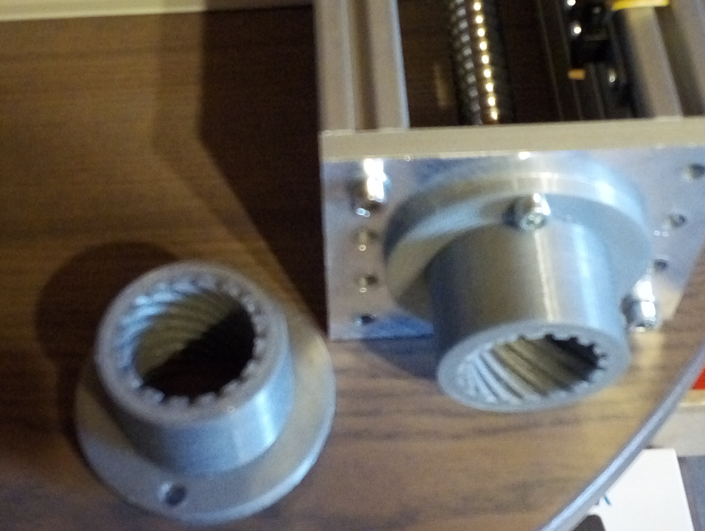
To prevent the pulleys for slipping, I sanded the machined end with two flat sides in an angle of 90 degrees.
the limit switch at the zero position is connected to a GPIO at the ODrive board. The upper position is actually open.
After initialization and finding zero position, the switches are only for emergency detection. I will try to use an GPIO of ODrive to show that initialization is finished and the control loop is running. This signal is used to connect both switches to a relais that can cut of the power.

 I hope the code deliberation is easier for you.

 only with a 150W power supply. Don`t know what happend with the final 1000W supply.