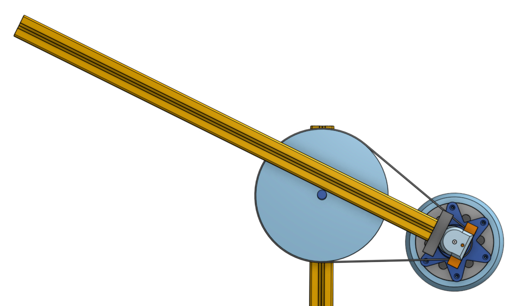
Project HoverArm

A new class of motor

The entire premise of ODrive is based around combining robotics control theory with cheap consumer grade hardware. Hobby aircraft motors were a convenient size and shape for gantry style machines, and mass produced enough to be cheap. However, many robotics applications require higher torque than the aircraft motors can put out. One way to overcome this limitation is to use a reduction gearbox, such as the concept explored by @Wetmelon:

However, moving beyond hobby aircraft motors, we find that there is another type of motor that has come to the consumer market in recent years. That’s right, I’m talking about Hoverboard motors:


A standard “6.5 inch” hoverboard hub motor, compared to the N5065 motor.

Hoverboard motors were already mentioned by @zwn in this thread several months ago, and recently I started looking into using them myself, and there are a few others over on the ODrive discord (specifically @beak90) who are also interested.

The first thing to note about these motors is that they are mass produced in large qantities, and they have enough torque to direct-drive a human, and humans are heavy. This means we can expect that it has a good torque-to-price ratio. Turns out, nope, it actually has a ridiculous torque-to-price ratio.


Torque vs Price plot, straight from the ODrive Motor Guide. Guess which one is the outlier.

We have yet to completely test the capabilities of these motors in this application, but we expect it to do somewhere between 5 to 10 Nm continuous, depending on cooling. They currently seem to cost about $35 new, and about $15 used (these numbers are on USA eBay).

Project HoverArm

As you may have guessed from the thread title, my goal is to use these motors to make a robot arm. The aim will be to make it very easy for anyone with access to basic hackspace equipment, like a 3D printer, to easily replicate. So it will use standard off-the-shelf parts, and 3D printed parts, and maybe a lasercutter (we’ll see about that one). No custom machined aluminium or anything like that.


Sneak peek of the design concept.

The design is looking like a 1200mm reach arm cabable of 3-5kg dynamic load and arbitrarily high static load (since the arm will be counter-balanced).

Join the fun

There are quite a few people in this community who are interested in building robot arms with ODrive, and so I invite you to join us. Feel free to comment on this design, or about hoverboard motors in general; or even better, get a $15 hoverboard motor for yourself to play with and build something cool.


Here are links that go directly to the rest of the write-up style posts:

  1. Hoverboard wheel motor teardown.
  2. Arm design concept.
  3. Drilling cooling holes.
  4. Links to future posts will appear here.
4 Likes

Teardown time!


Here we have our specimen, a new hoverboard motor.


First thing I noticed is that it’s really heavy. Specifically, it’s 3146g heavy.


Next, let’s crack it open. There is a bearing between the aluminium plate I’m trying to get off and the shaft. This is press-fitted. I think on some models you can easily pull the cover off, but it was pressed on hard in my case and would not come off by pulling.


Yes those are door stoppers… You can see the stator starting to peek up there. Since my motor would not separate at the shaft-to-plate interface, I had to pull the stator out of the rotor, and therefore fight against the strength of very very strong neodymium magnets. If you try this yourself, I warn you, the pinch risk is real and terrifying.


After some thorough convincing by the hammer crowbar end, a flat head screwdriver and peices of wood as levers and spacers, I managed to get the stator out.


Stator and cover plate together weigh 1630g. From weighing the whole thing before, we know the rotor weighs 1516g.


Photo of stator.


Another photo of stator.


More photo of stator. Here we can see the hall effect sensors used to do the 120-degrees block commutation as is customary for very basic brushless controllers. The stator has 27 slots/teeth/coils.


Here is the rotor. We count 30 magnets, so it’s a 30 pole machine.


So we have a 27 slot 30 pole machine, aka 27N30P. Above is the analysis of this configuration by the Emetor Winding Calculator. Each phase is wound in alternate polarity around three consecutive teeth, then the next phase is, and so on, as per the diagram. One interesting thing to note is that this motor is equivalent to a 9N10P motor repeated 3 times.

Measurements


I did the drill test, and got the above trace. First thing to note is that the back-emf is very nicely sinusoidal, I’m starting to like these motors. The trace shows 17.2V peak-to-peak, and 34.36Hz.

Let’s calculate the kv rating of the motor.
Hobby motor kv ratings are measured in RPM/V. However, this is actually a little ambigous: what votage are we talking about? Specifically it is peak line-to-line voltage (aka phase-to-phase voltage). The scope probe was on one phase, and the scope ground was on the other, so what we just measured was exactly this voltage, which is great. So the peak voltage is 8.6V, half of the peak-to-peak voltage.
We know that the electrical frequency was 34.36Hz. We know that the electrical frequency is 15 times faster than the mechanical rotation speed, since we have 15 pole pairs (30 pole motor). So the mechanical rotation was 2.29 rotations per second, or 137.4 RPM.
We simply divide the speed by the voltage to get the kv value: 137.4 RPM / 8.6 V = 15.98 RPM / V.

That is extremely low compared to most hobby aircraft brushless motors, even the big ones have kv values in the 100 RPM/V range.

The next thing to test is the phase resistance. I don’t have a picture of this, but the setup is basically to connect a bench power supply across one phase and another phase. I set the supply to current limit to 4A and it put the voltage at 1.36V. Assuming a wye connected motor, each phase only drops half of the voltage, so 680mV each. This gives a phase resistance of 680mV / 4A = 170 milli-ohms.

4 Likes

Great posts Oskar! As you mentioned, I am also working on making some robots with these motors. I got some motors in the mail yesterday and did my own teardown. You can find my teardown on my blog: http://blog.kyleb.me/2018/01/hoverboard-motor-teardown.html

My motors look fairly different from Oskar’s. Mostly in the windings. I think this will be a common occurrence, since they are manufactured by many different factories. Unfortunately they is pretty much no way to tell exactly what you’re getting, since sellers just market this as a generic hoverboard motor. So for robotics projects, probably just buy all your motors from the same place, so that kV values and motor sizes are the same for all the motors in your project.

Also, this is a reminder that if you don’t see updates in this forum or on my blog, that doesn’t mean that we aren’t working on stuff. We tend to have lots of discussions on the Discord chat, since it is easier to have longer, quicker discussions. Feel free to join us! Projects like this are discussed in the integrations channel.

2 Likes

I’m really interested in these motors. @madcowswe please could you say what’s the mean diameter of the rotor is to estimate the moment of inertia?

Yes, sorry I should have included that in the teardown post, since I did actually calculate it.

The distance of the labelled point from from the rotation axis is 68mm. Using the mass we have from before, we get a MOI of (68mm)^2 * 1516g = 0.00701 kg m^2.

This means that if the motor can put out 10Nm, we can spin it up to 800 rpm in 60 ms!

1 Like

Nuts!

If you do ever put a custom enclosed motor in the store, I’d base it one of these beasts. Servo motor and epicyclic gearbox manufacturers the world over will close their doors overnight.

1 Like

Arm design concept

So we are trying to make this thing as cheap as possible while still being quite capable. Therefore, no fancy gearboxes, just a single belt transmission for each axis. Also, to increase the payload capacity, we will be adding counterweights to the reverse side.

revese
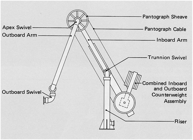
The original design inspiration for this was a counterweight balanced floor lamp that I saw at my cousins house. I can’t find a picture of that, so this is the most appropriate design I could find. It is a loading arm for connecting the pipe used to load tankers, so feel free to disregard the nautical terms on the labels.

The above design is fully balanced when there is no payload. We can also change the counterweight mass, or move the pivot points, to fully balance the arm with a specific static payload. If we are going to be picking up and dropping things, i.e. if we have a dynamic payload, we can borrow a trick that is very commonly used in elevators, and that is to over-counterweight the arm (elevator). That is, when the arm is empty, it actually has to work to keep the arm down rather than lift up: this larger counter-weight means we get a higher max capacity.


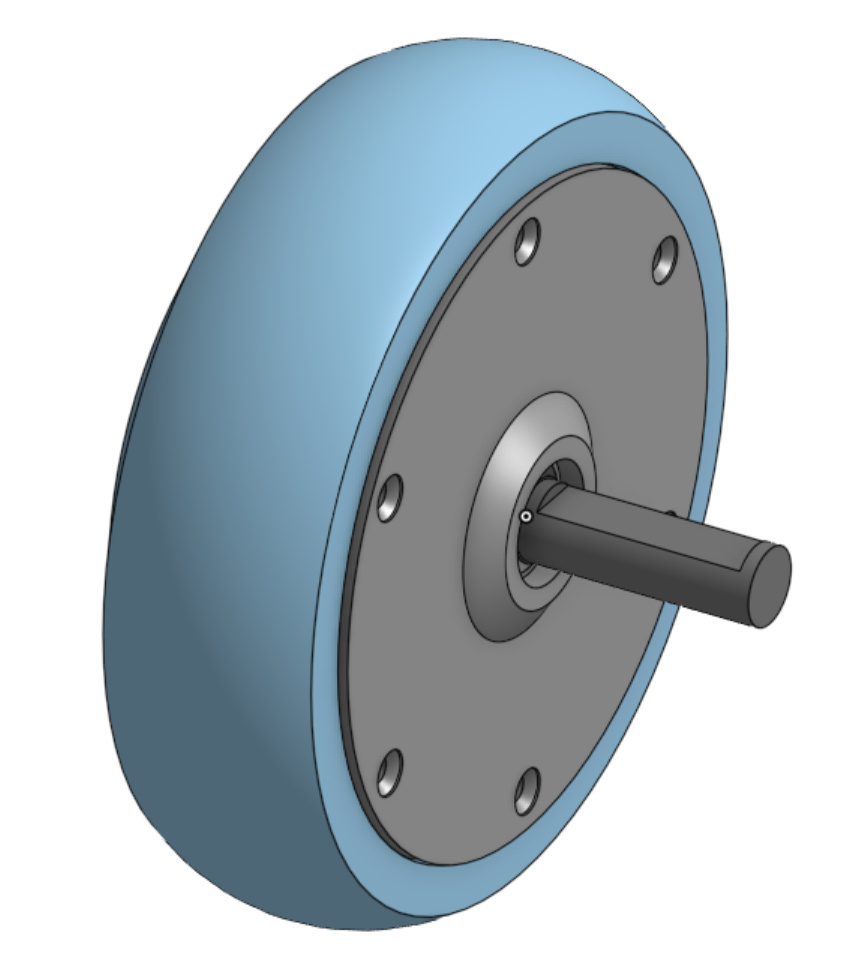
Very conveniently, a belt drive transmission and the hoverboard motor being quite heavy, means we can neatly let the wheel itself be the counterweight; and we can always add more weight if we need to. This concept so far only shows one axis, but we will be stacking the other axis just like in the marine loading arm concept above.


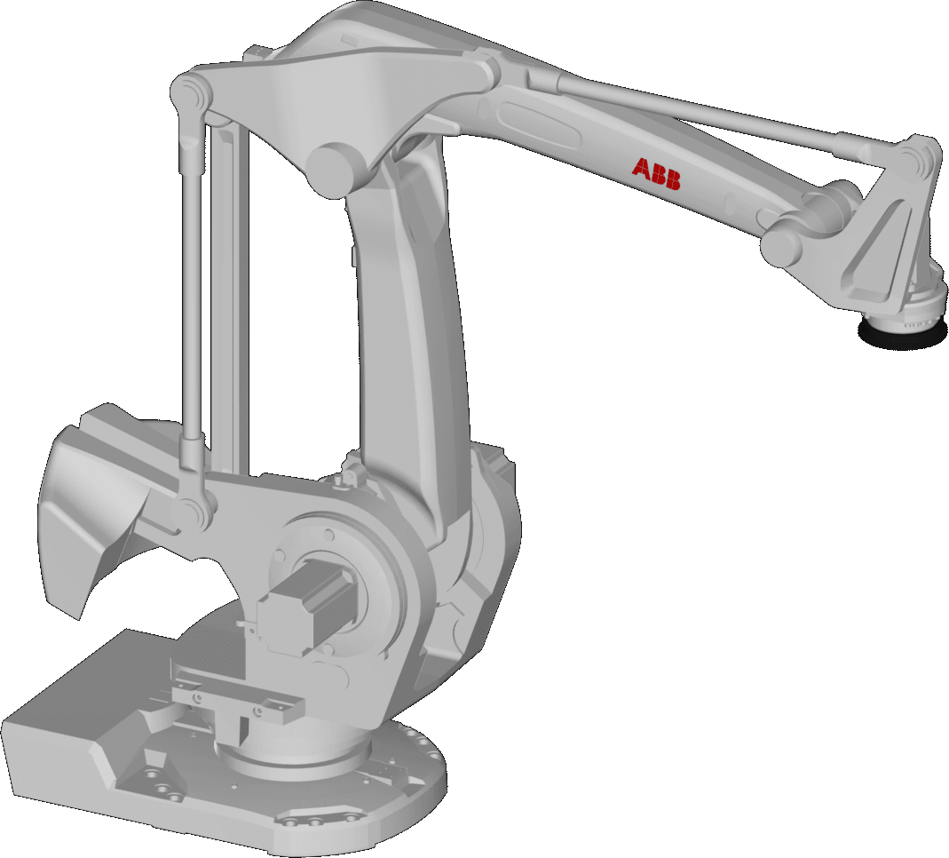
Unlike the marine loading arm, we wont use cables to connect the outer limb, instead we will use a solid rod like the above ABB IRB-760 palliating robot. This robot has another linkage mechanism (the sets of slightly thinner linkage rods). This is used to maintain the end of the robot in the horizontal plane without any additional active axes. I think I will try to do this also for my design, but I don’t really have a plan of how it will be done just yet. Feel free to provide suggestions.

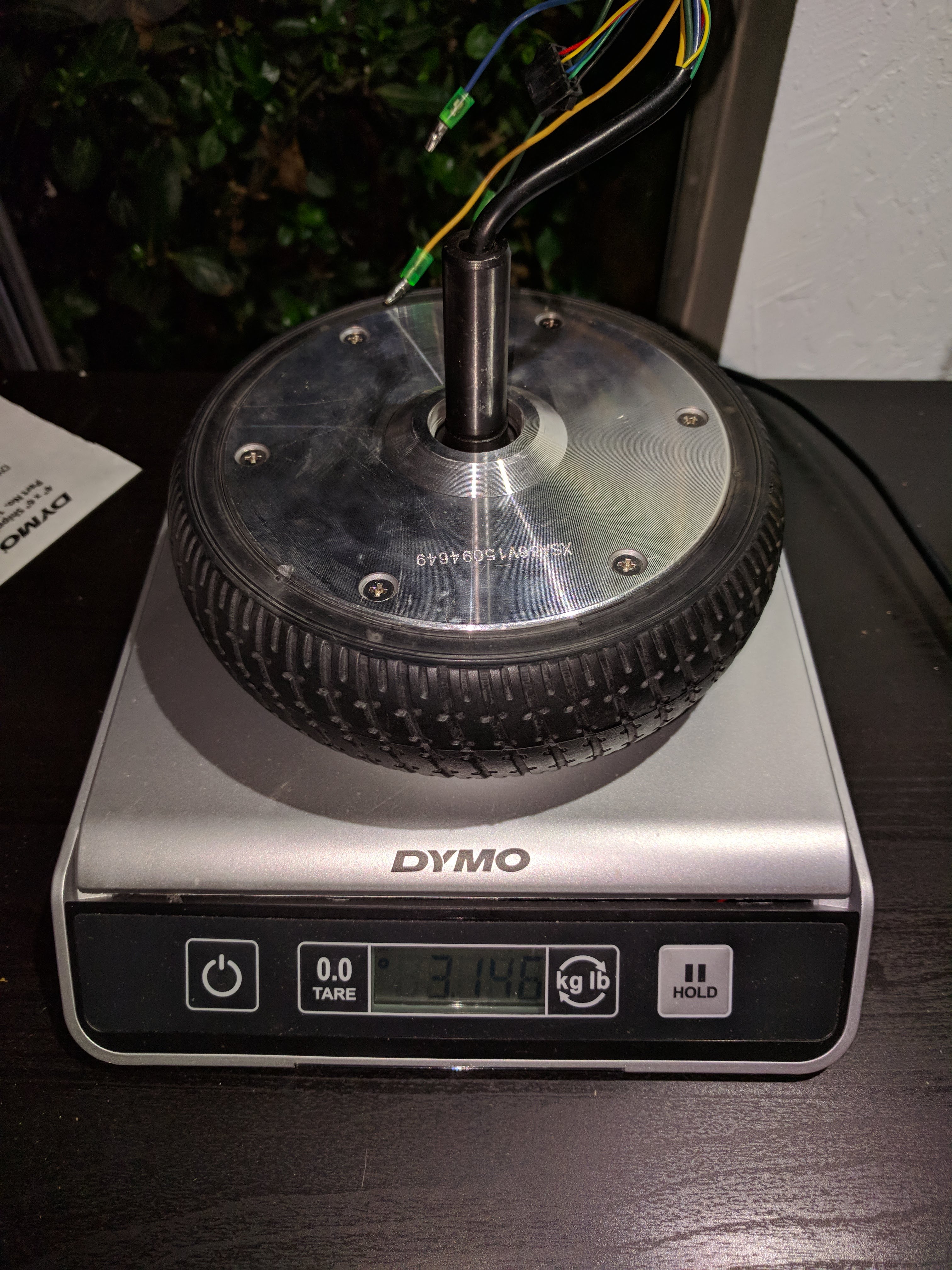
Getting the torque out of the wheel

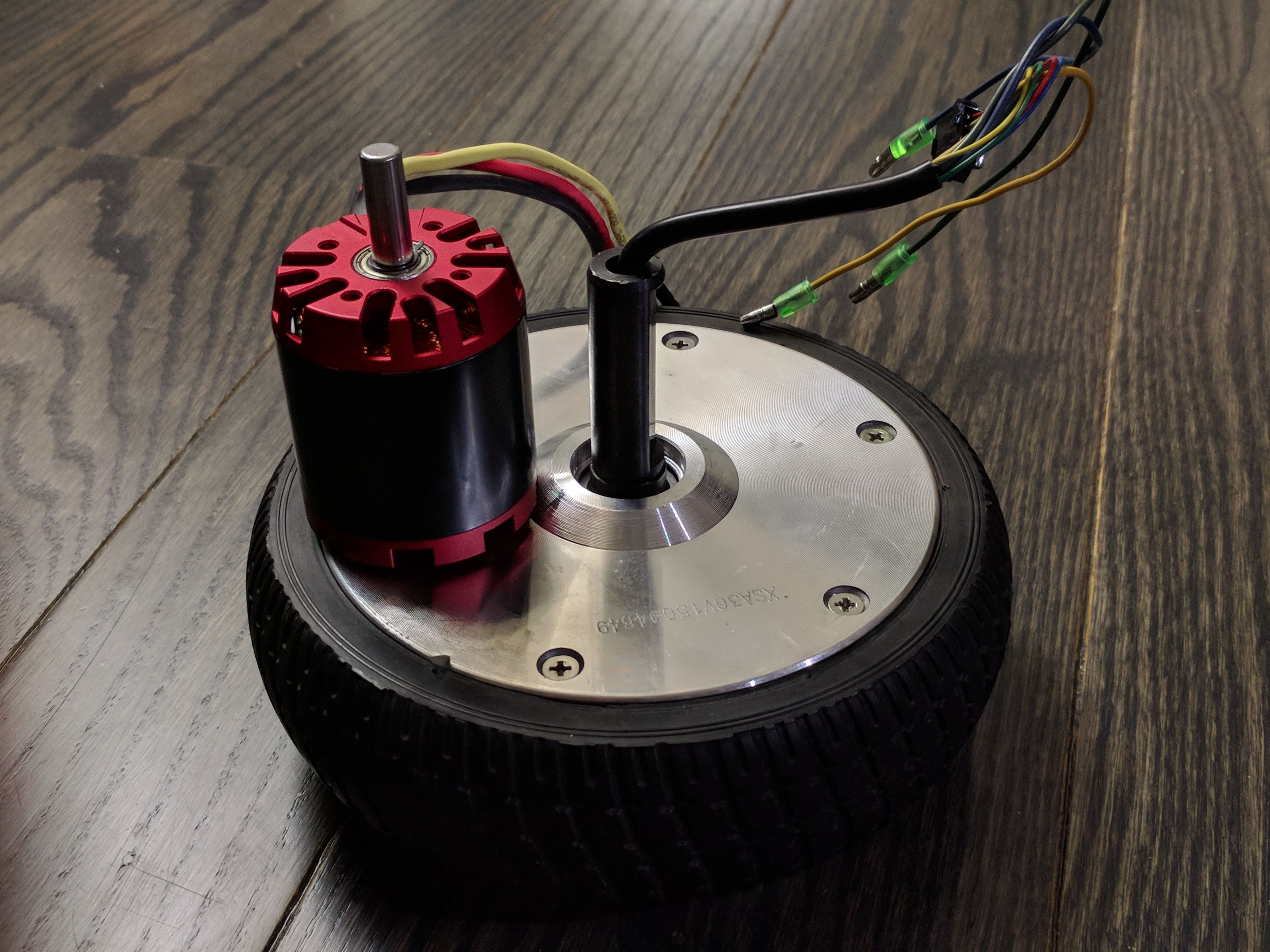
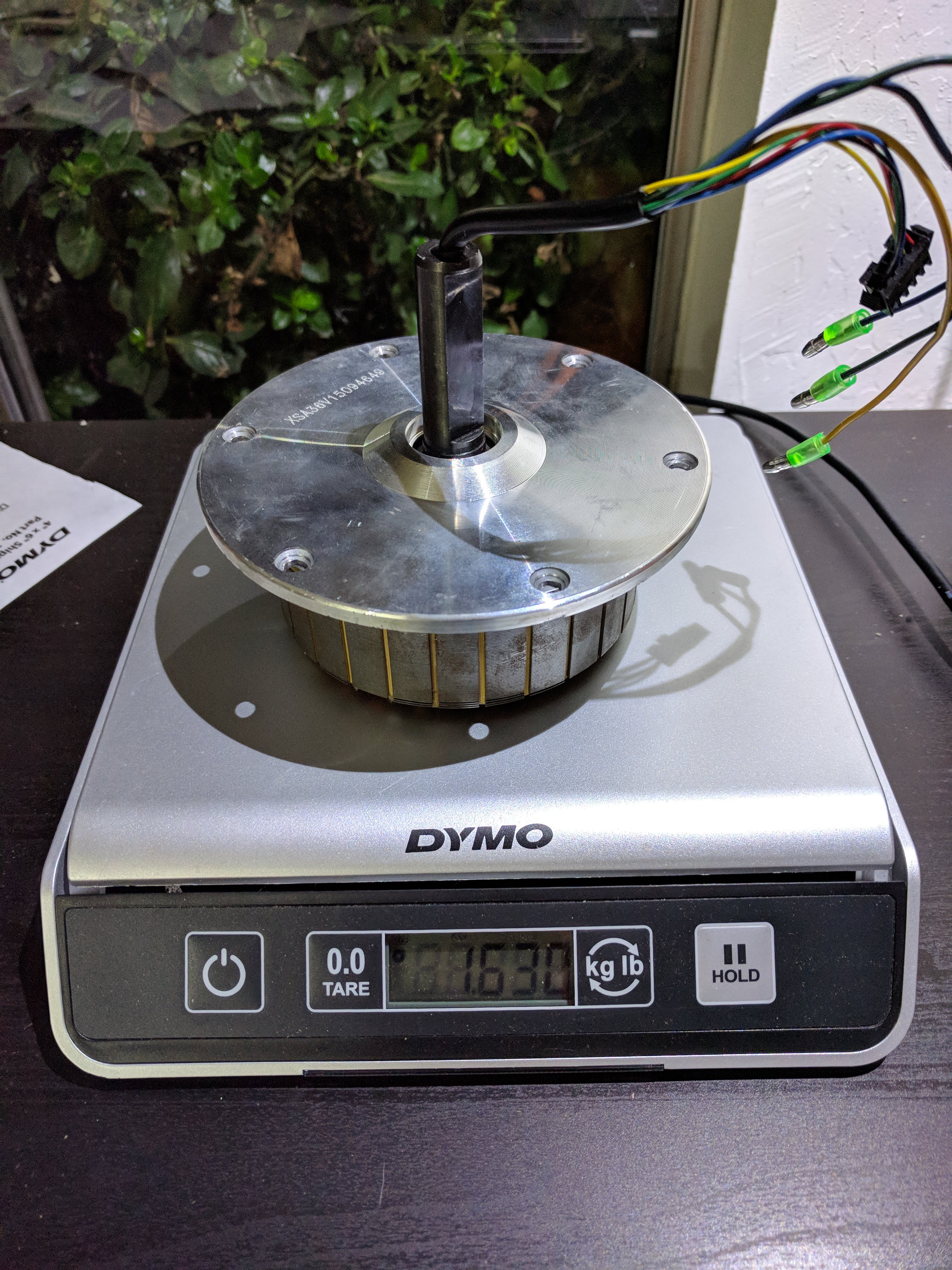
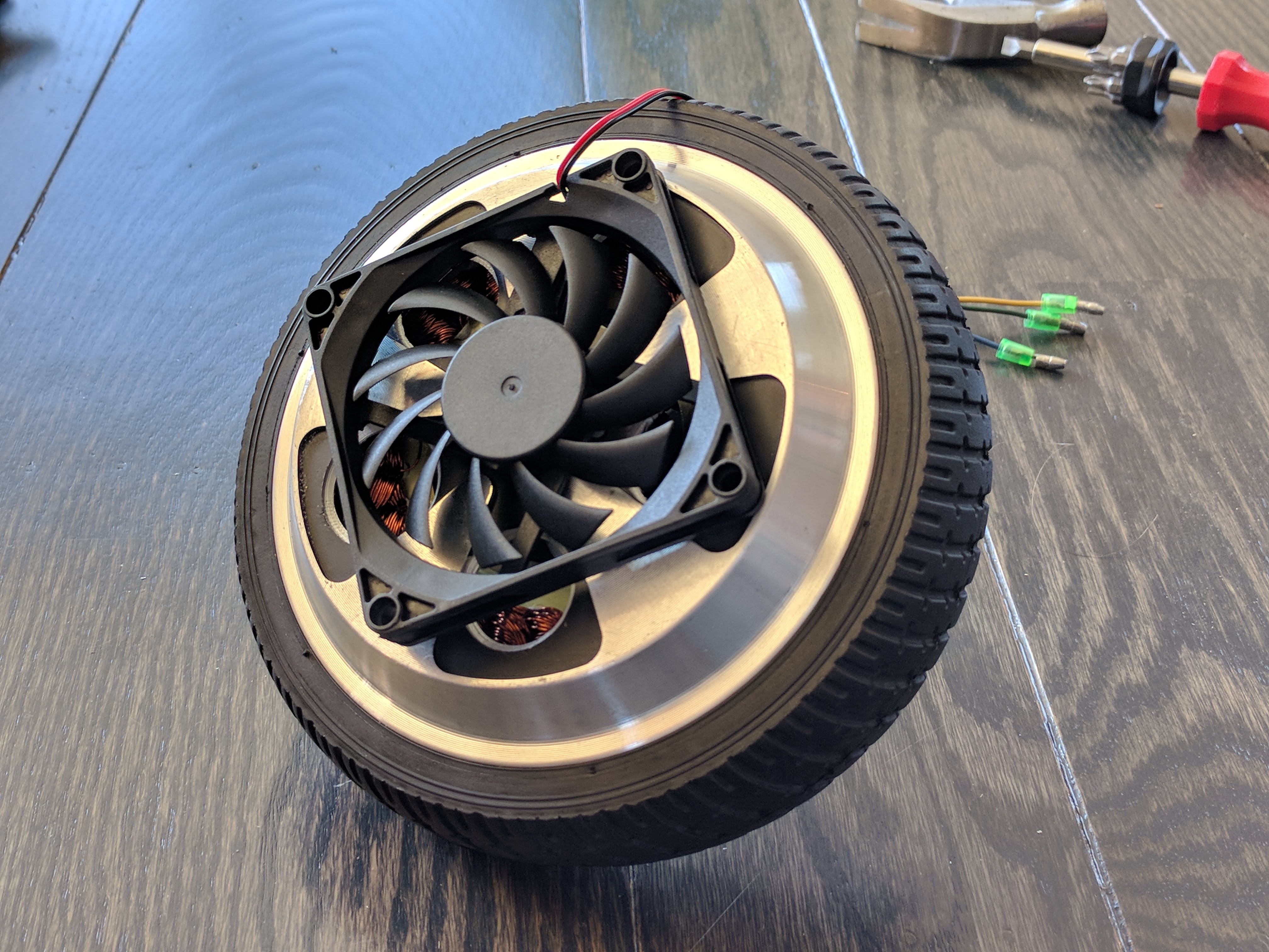
Okay so this is the main disadvantage to these hoverboard motors: they are designed to spin a rubber tire on the ground, not coerced into powering robot arms. Nevertheless, here is my plan to try to convince them to do so anyway:


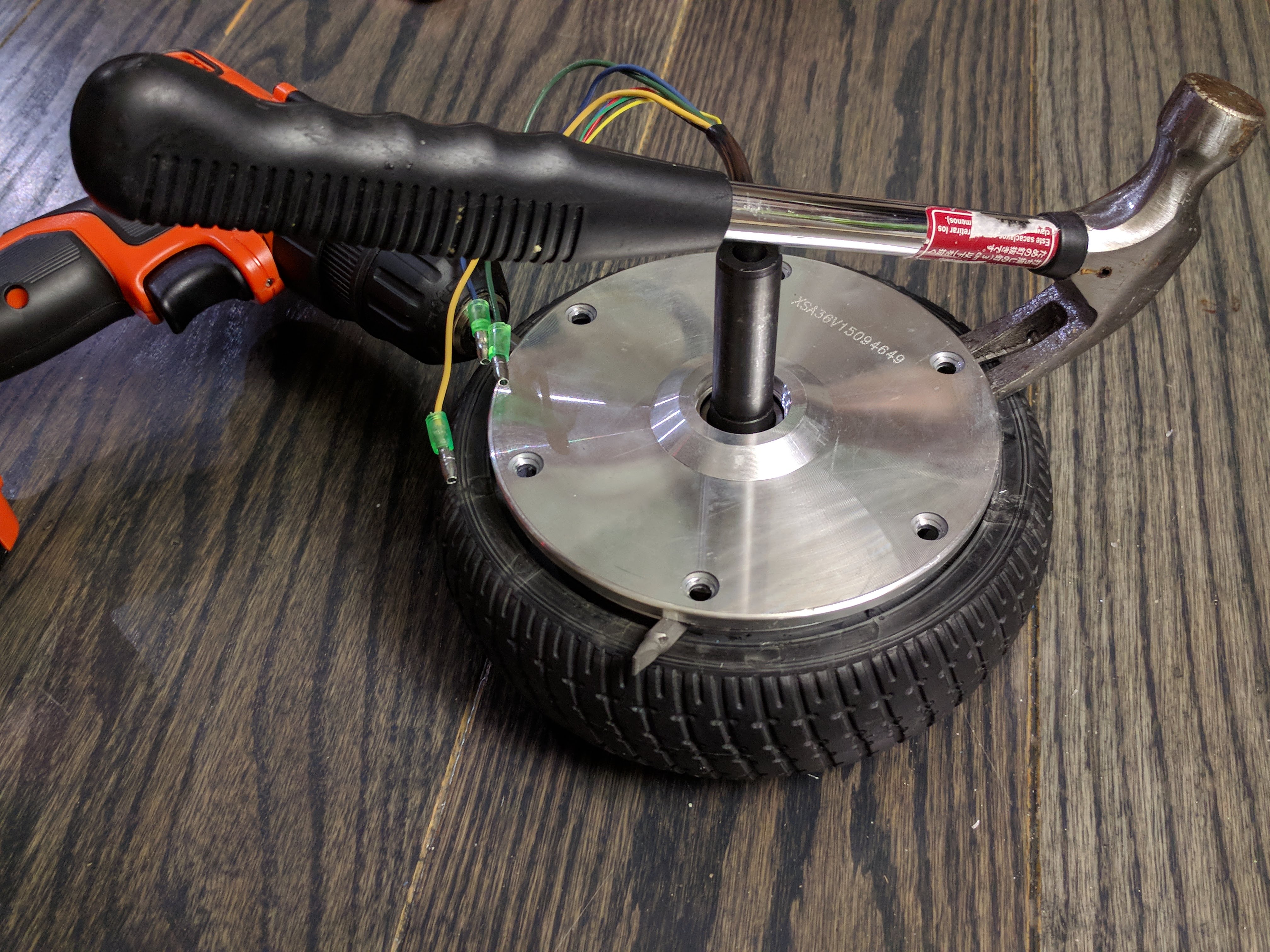
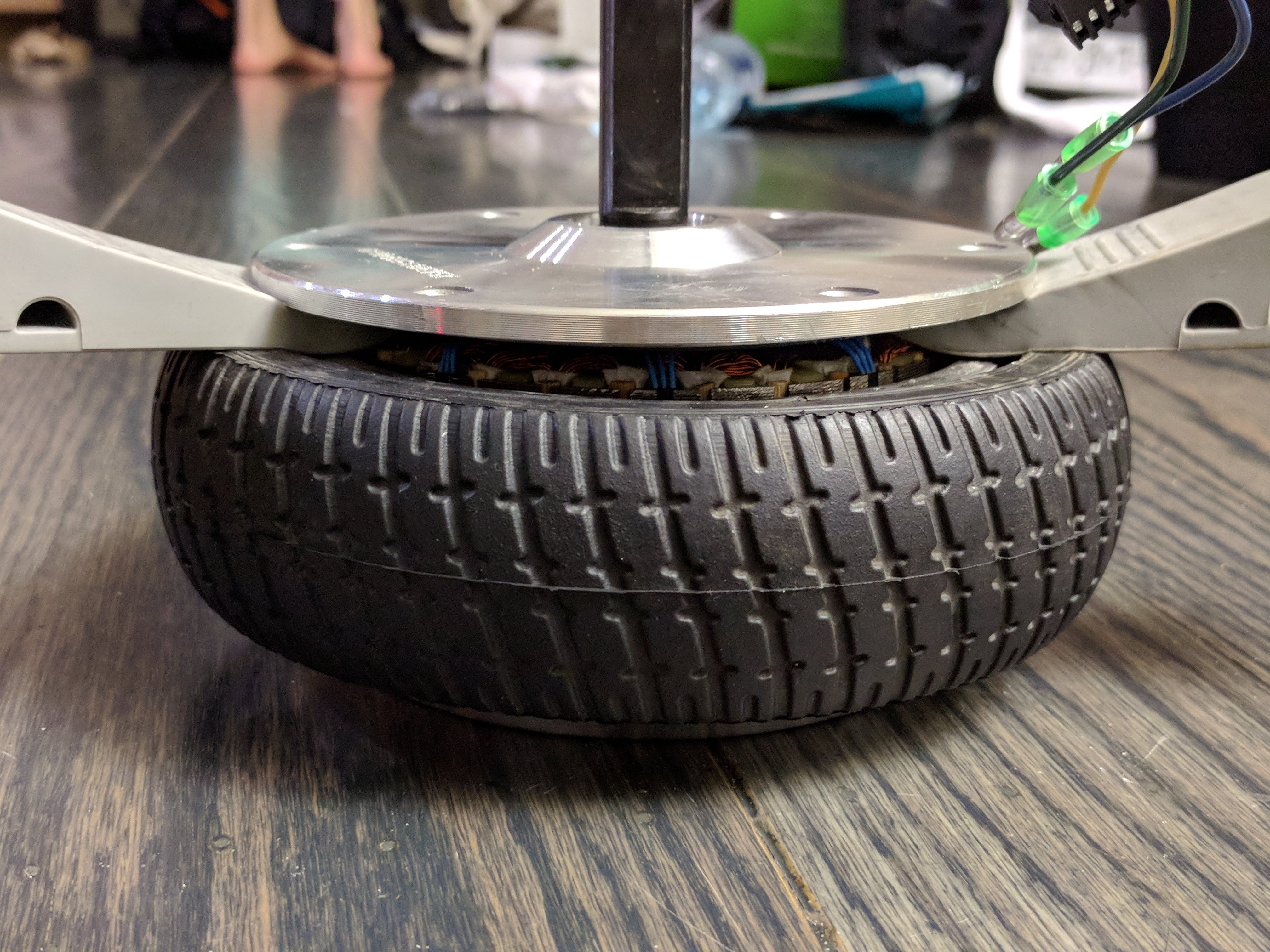
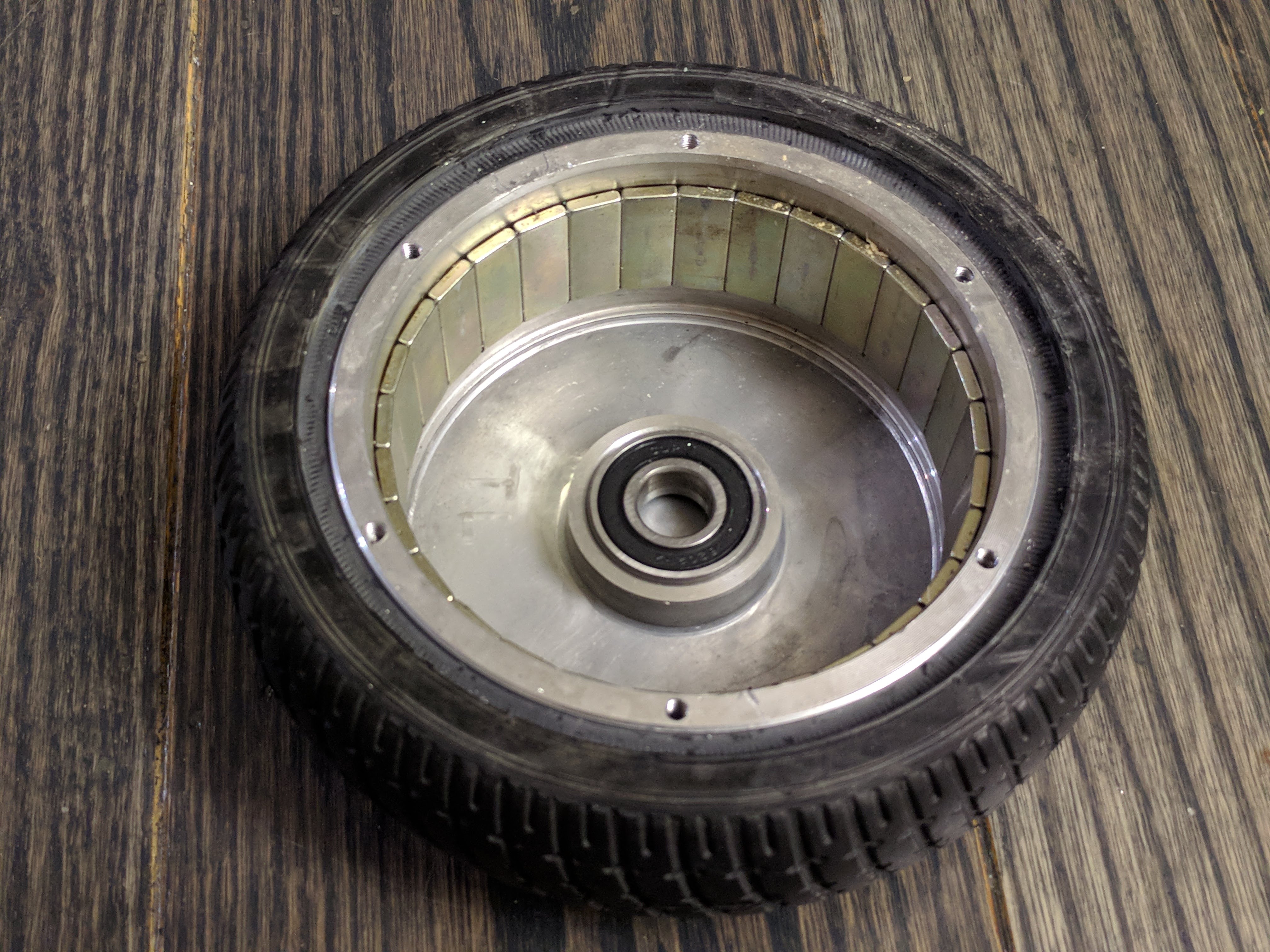
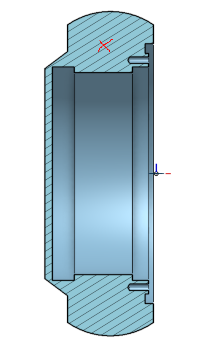
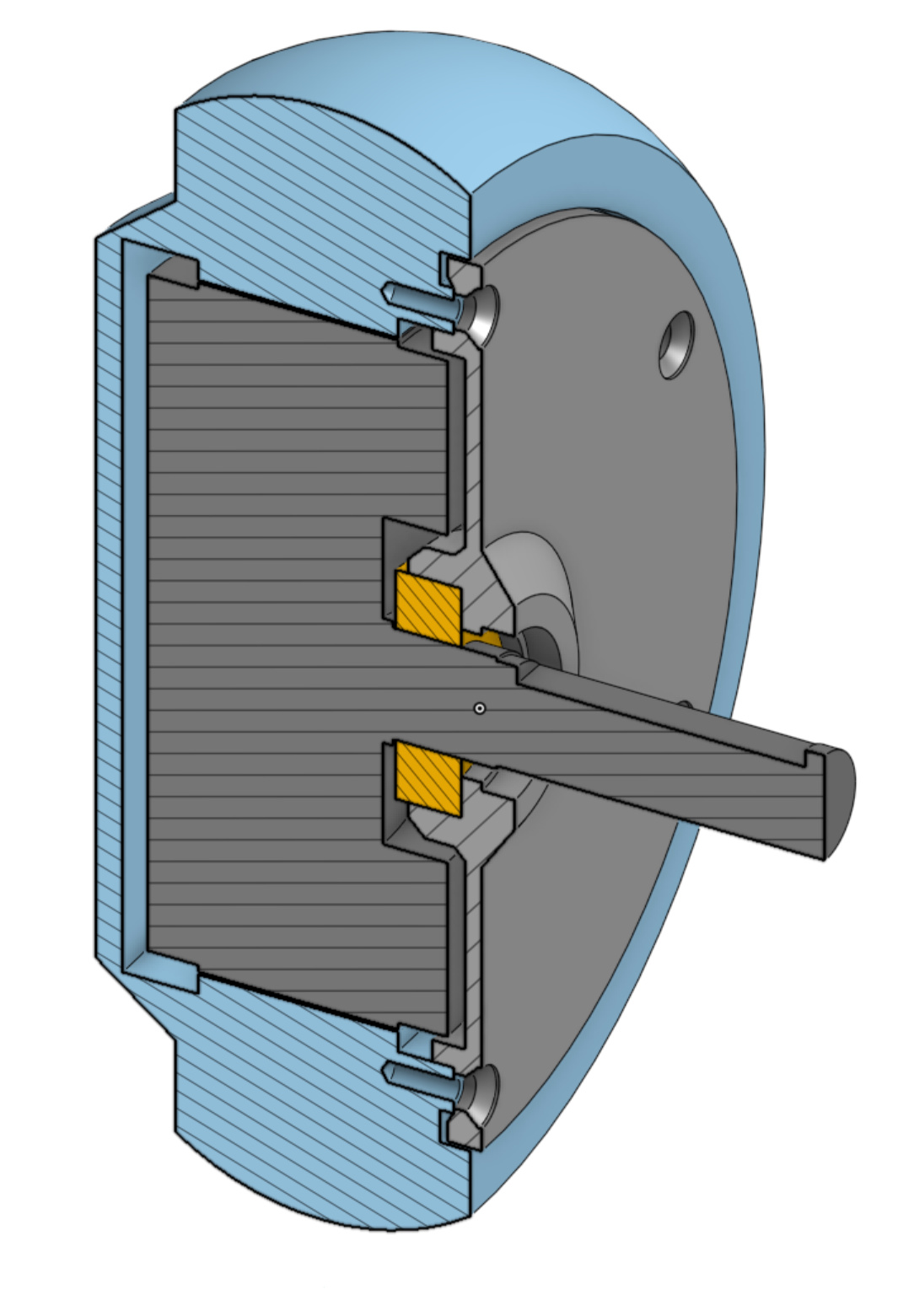
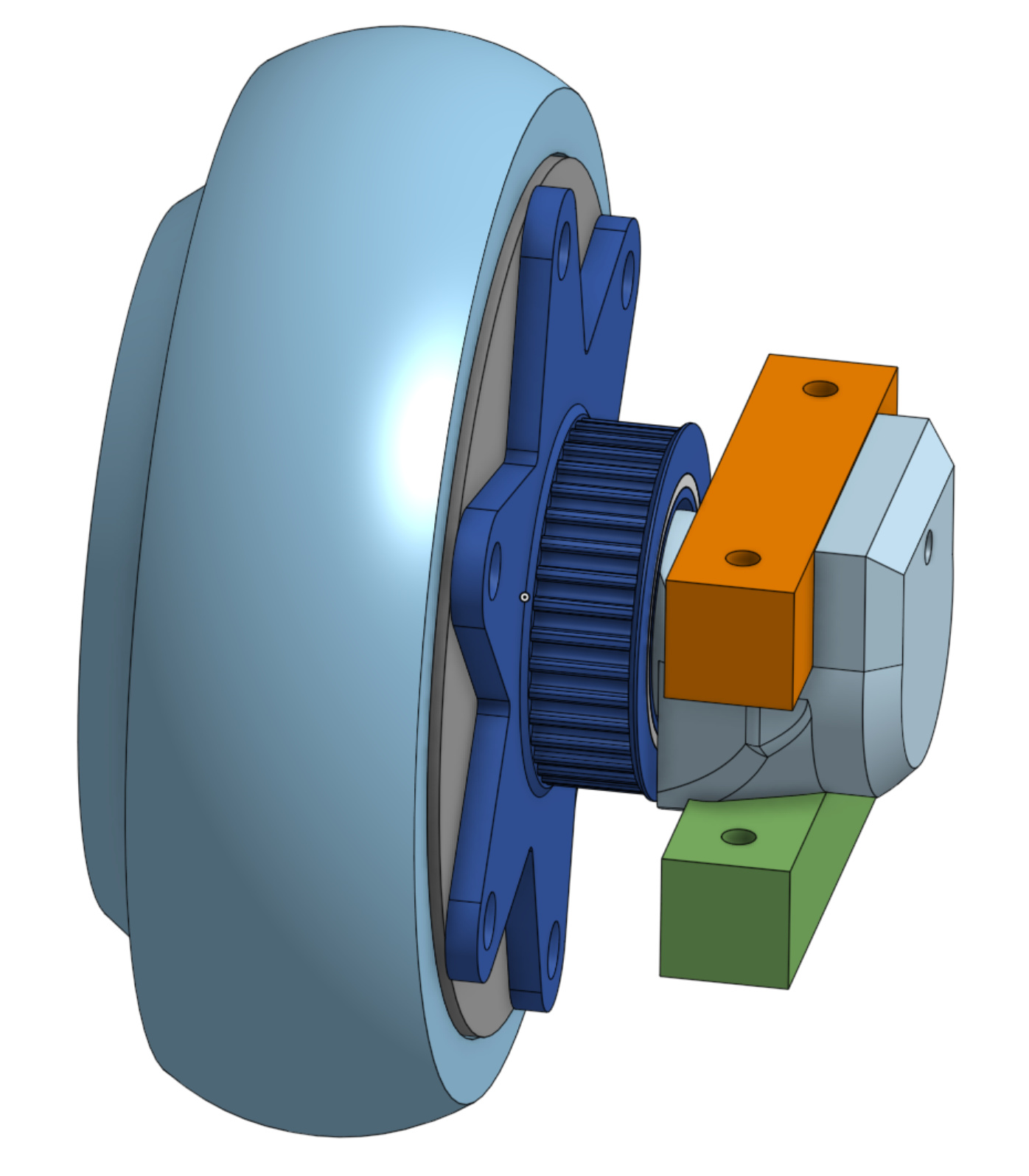
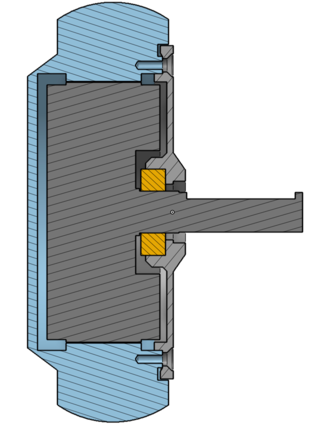
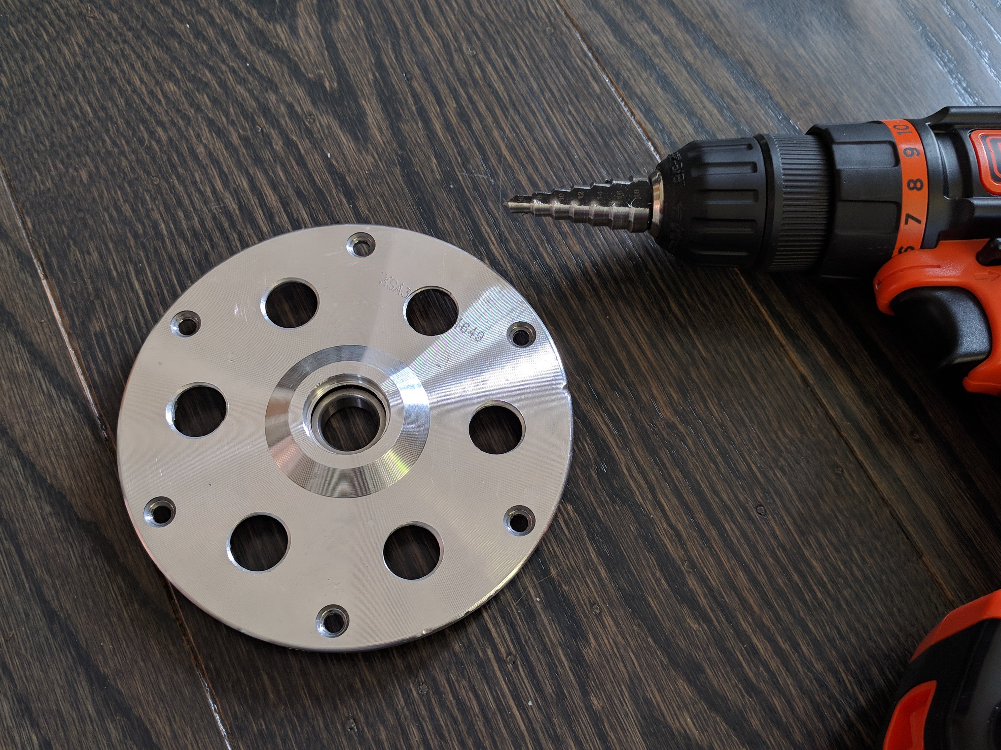
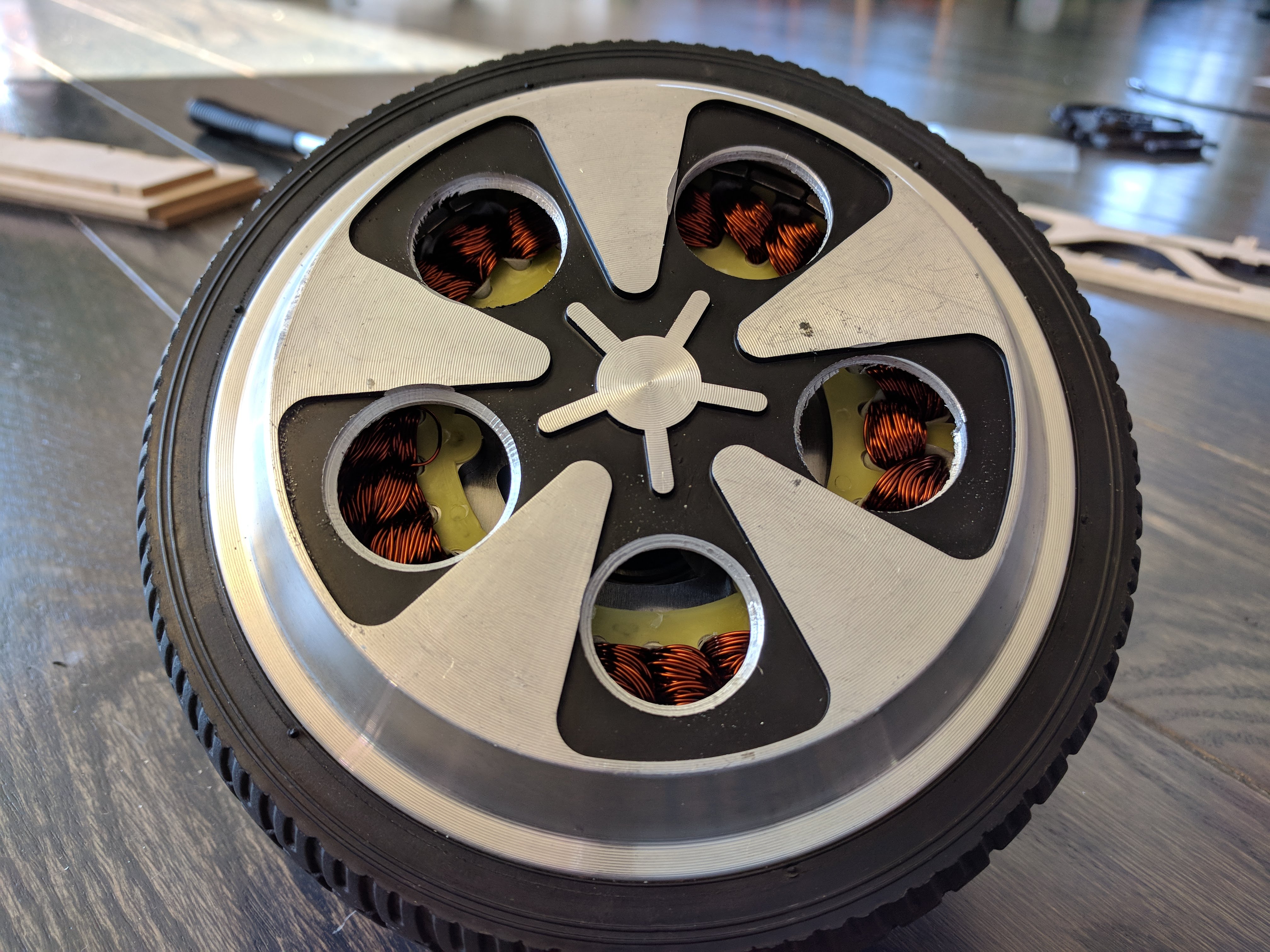
The first thing we need to think about is how to get useful torque out. Lucky for us, on the rotor side we can use the 6 screws that hold the cover plate onto the wheel.


Light blue: main rotor shell, light gray: rotor cover plate, yellow: bearing, dark gray: stator.
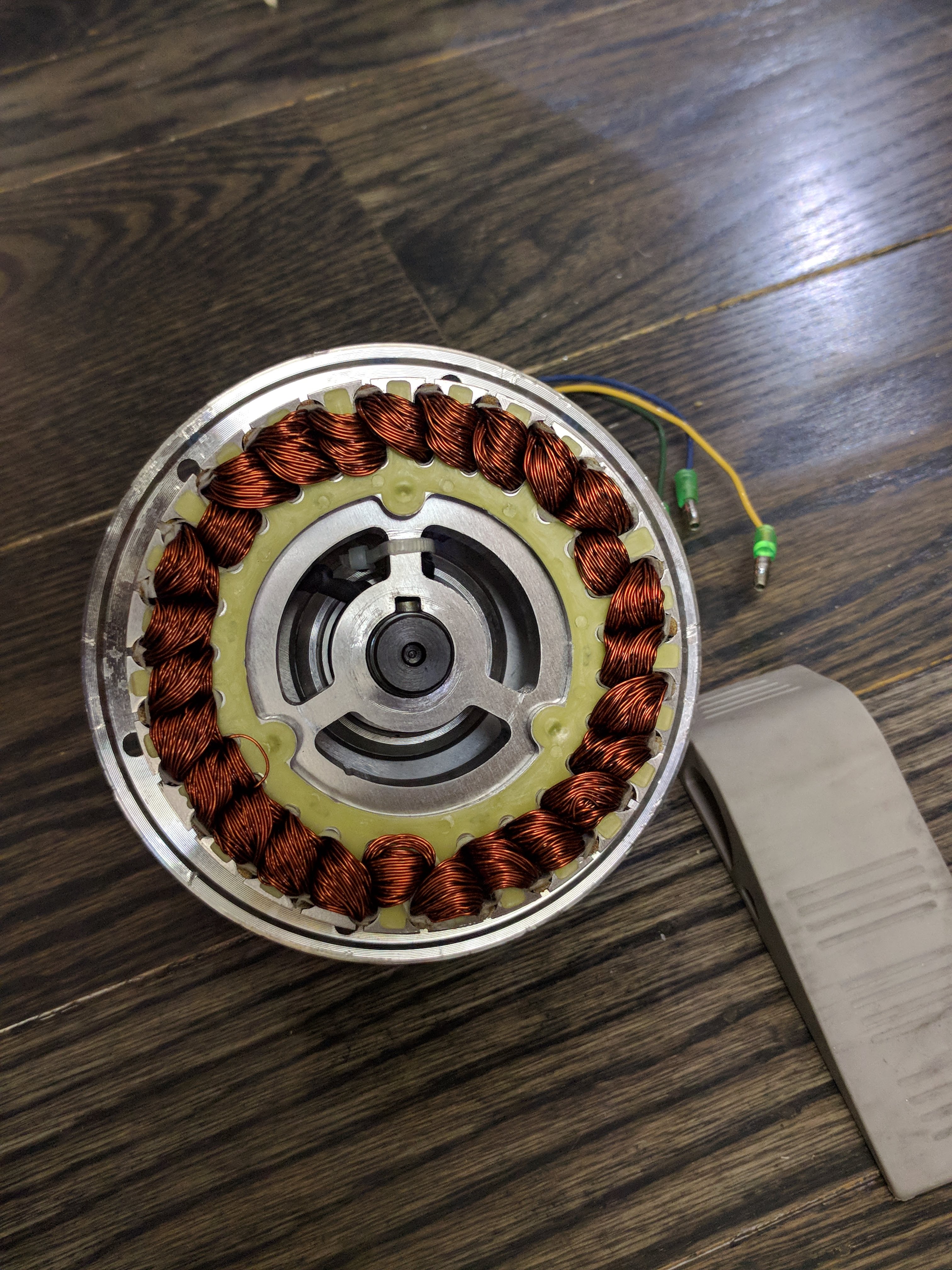
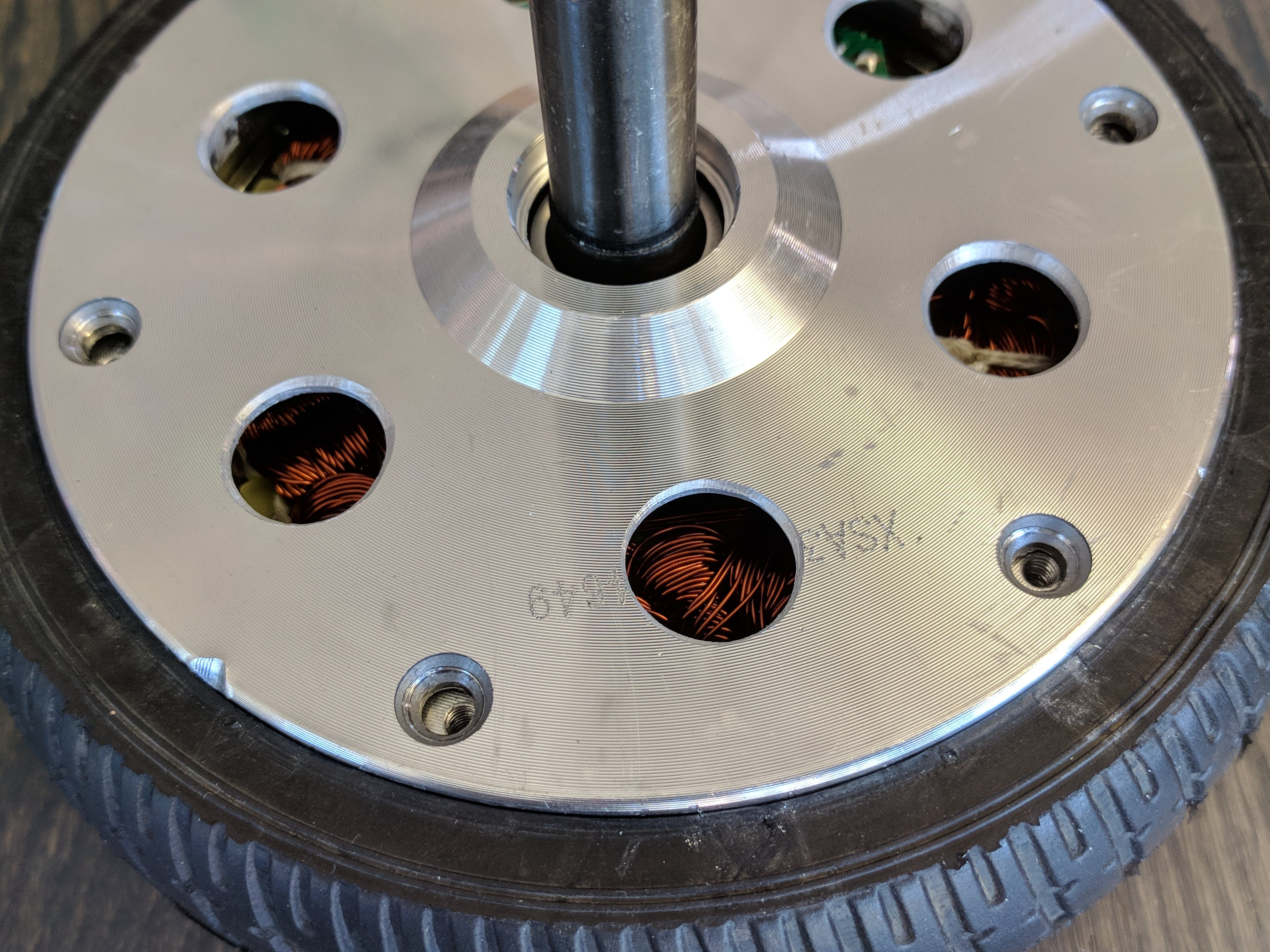
On the stator side, as you can see the only thing we have available to hold on to is that shaft with the flat on it. That’s gonna be much more tricky without using machined metal parts. Maybe it won’t work, but we are here to find out.


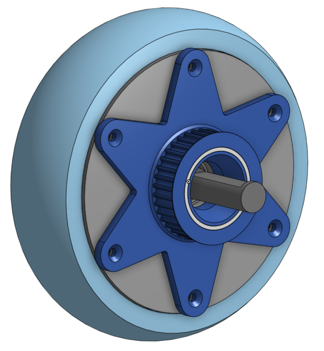
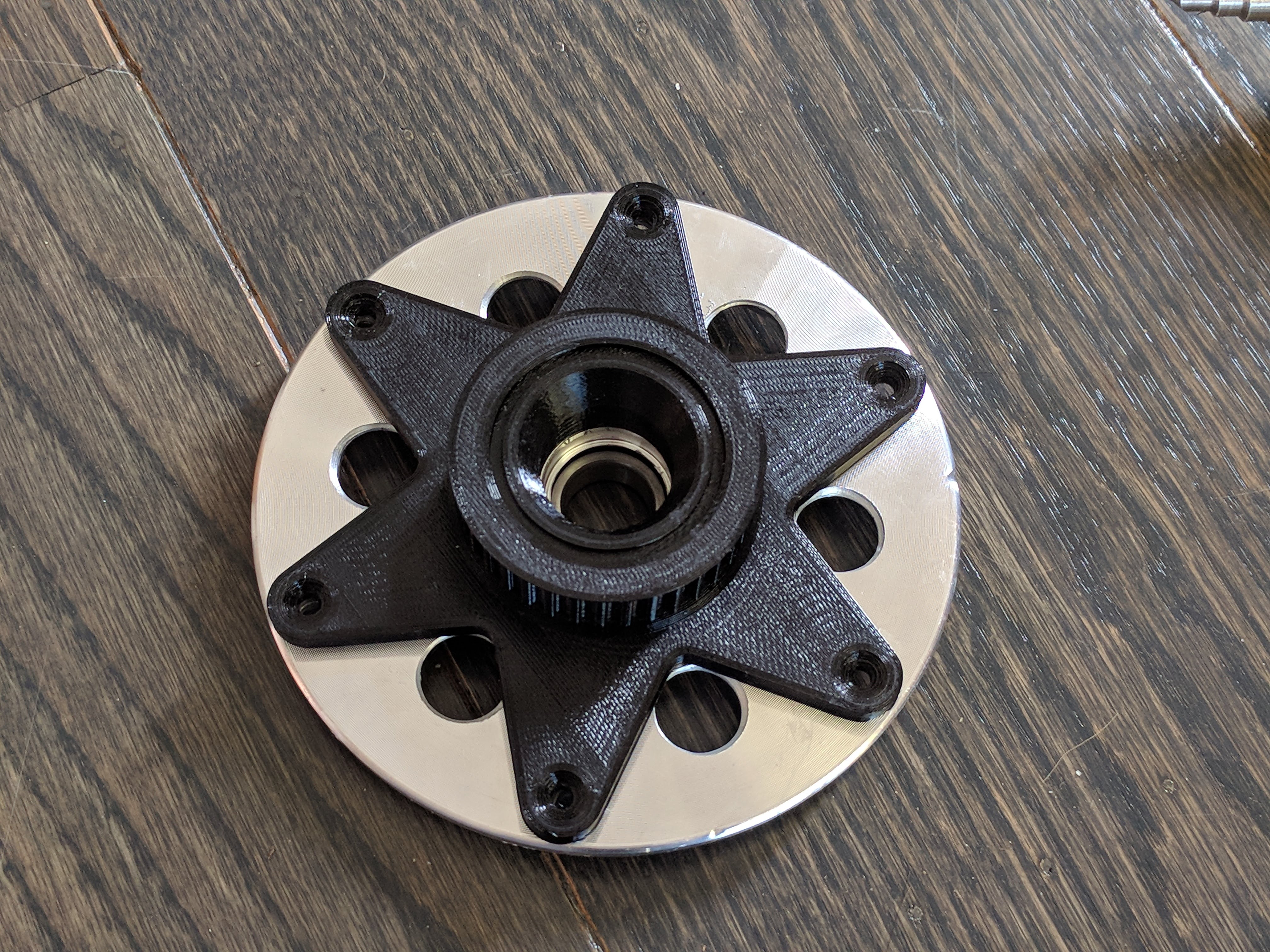
This is the pulley starfish, it is intended to be 3D printed. Substituting the original screws for the rotor cover with longer ones we can attach it in the 6 locations. The pulley is a for a GT2 profile 5mm pitch 15mm wide belt. The gray ring is for the encoder, which I will talk about at the end of this post.


I think there should be enough material, at least when using solid PETg, to handle a fair bit of belt tension. The underside of the starfish has to be flat to allow sitting on the print bed, otherwise I would have made it fill the original countersinks of the cover plate. We can make some separate filler rings for that I guess.


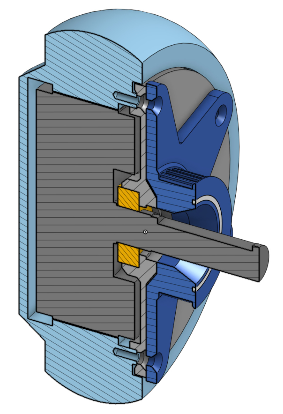
So here is the part that I am the most worried about, the one that will hold onto the shaft.


It will be made out of printed solid PETg plastic.


It will hold two pieces of 2020 aluminium extrusion that are clamped together with two screws.


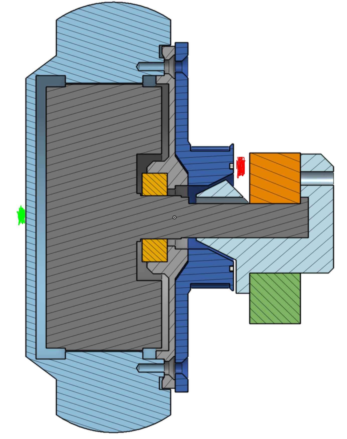
The top extrusion will be located against the flat of the shaft to transfer the torque. The belt tension will be pulling the pulley “down” in this view, so the interface to the orange extrusion should be under compression. So there are two things I’m worried about: will the small area to the orange extrusion be enough to handle all the torque, and will the light blue plastic part be strong enough to hold the tension of the belt cantilevered so far out?

Feel free to look around in the Onshape document and let me know what you think. This is the live document that I will be working in, so it things may change by the time you look.

Encoder

These motors have hall sensors, but we need more accuracy than that for this. So we need to install an encoder. A shafted or shaft-fitted encoder is mostly ruled out, since it will be quite annoying and awkward to bolt a flange-and-shaft part to the “outside” face of the motor. Two feasable options are on-axis and off-axis magnetic encoders, since you only have to glue a magnet to the rotor, which is fairly easy.


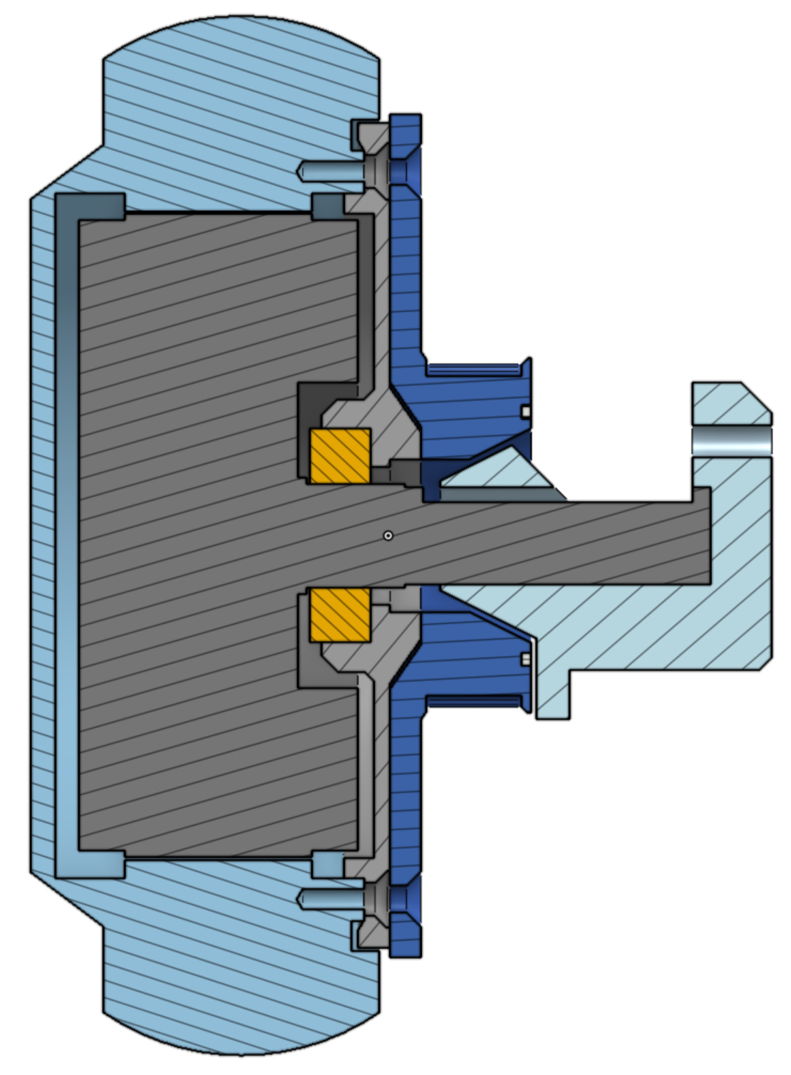
With an on-axis encoder, we would glue a diametrically magnetized magnet to the only on-axis location that is available, namely the location shown above in bright green. The other option is to use a off-axis encoder in a location ext to a rotating face, such as the location shown in red.

27174-6997799
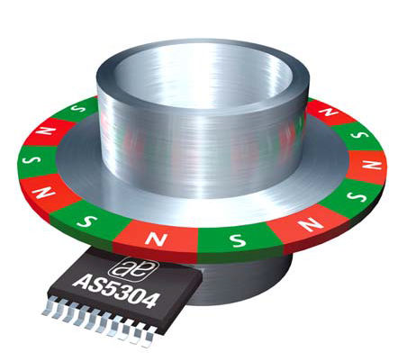
These off-axis encoder magnets are often multi-pole, meaning they show multiple “magnetic” rotations per mechanical turn. The drawback of this is that you don’t get any useful homing functionality from the encoder index pulse. The upshot, however, is that you can make the pole count really high, and get a very high resolution encoder.


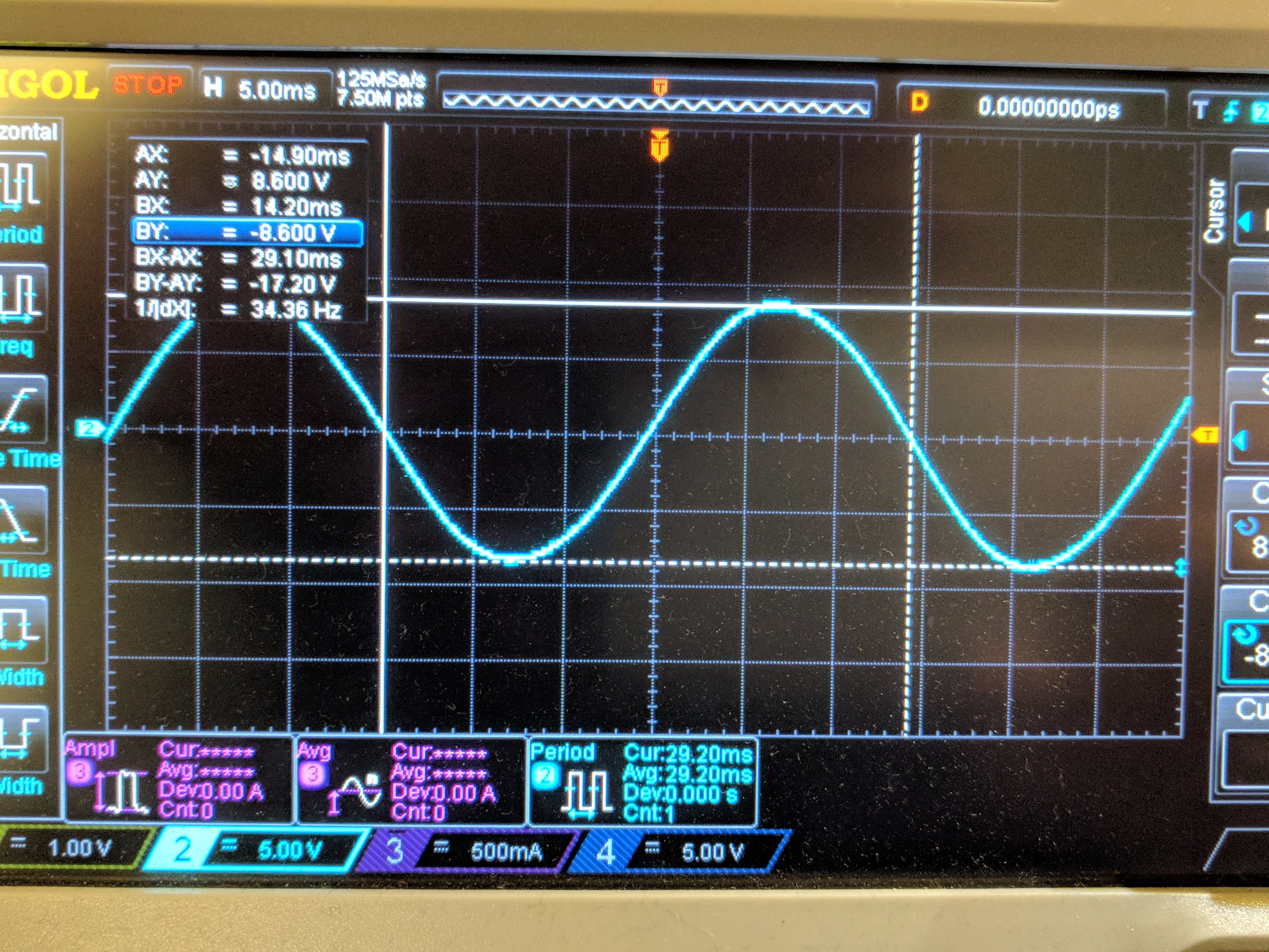
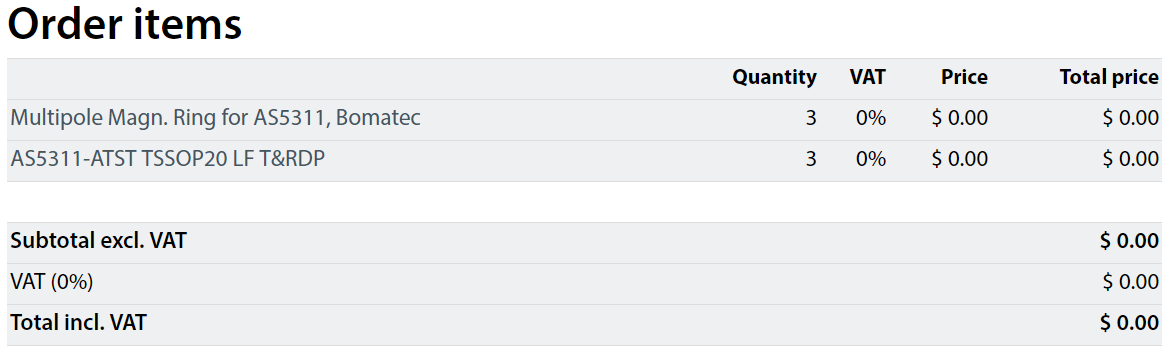
Free samples are the best. We will be trying out the AS5311 encoder with a 128 pole magnet ring. The encoder outputs 10 usable bits per pole-pair, so that means we have a 65,536 count/rev encoder. Yes I also didn’t quite believe that number when I first saw it. Incredibly, the cost of these parts are like $10-$15 in single quantity! Crazy. Let’s hope it lives up to the specs.


Not only were the samples free, but they got here from Austria in 3 days. These guys know how to impress a customer.

1 Like

Cooling


If you look closely at the stator, you can see that it has an airgap all around it, except for the connection to the shaft.


But even there, actually, it’s pretty much air-gapped.

This means that by default, the cooling of the coils will be very poor. I think in the original application there was not so much that could be done since the motors needed to be sealed against water and dirt ingression.

Drillin’ Holes


Let’s get one thing straight, stepped drill bits are awesome.


Yep, looks like some air will get to the stator.


I did a test-print, and it’s starting to look less like a hoverboard wheel and more like… I don’t know what, but not a hoverboard wheel. Looks cool though.


On the other side where there is no starfish, we can make big holes! Next time I would probably put them slightly further out. I doubt it makes a huge difference though.


Since the wheel should only spin a couple of turns, we could even add a fan here. This fan is just for illustration, it is completely the wrong size. Not sure how I would attach one, maybe just glue it?

2 Likes

Also look at direct drive electric bicycles… 48V 35 NM motors…

Do you have a URL for the ebay item?

Yep, here.

also take a look at skateboard wheels and scooter wheels

https://www.aliexpress.com/w/wholesale-motor-wheel.html?spm=2114.search0104.0.0.6161bbd0fCg2aG&initiative_id=RS_20180202144249&site=glo&groupsort=1&SortType=price_asc&g=y&SearchText=motor+wheel

https://www.aliexpress.com/w/wholesale-BLDC-wheel.html?spm=2114.search0104.0.0.56e9f031oV8IMV&initiative_id=SB_20180202144241&site=glo&groupsort=1&SortType=price_asc&g=y&SearchText=BLDC+wheel

readily available up to 800w

would it make sense to put your belt adapter on the other side of the wheel so you have better access to the shaft?

Also, how about removing the rubber wheel and 3d printing belt drive segments that you glue/screw into the hub?

1 Like

I had two of these arrive yesterday…

Not sure what to expect in terms of newton meters. 35KV, 35 peak amp with your 48V controller and encoder.

Hm, I think Hobbyking has an error on their spec page. Ohms law dictates that these two statements are mutually exclusive:

  • 8.1 ohm phase-to-phase.
  • 35A current rating.

Unless you are driving it with 210V power and dissipating 11kW of losses. Maybe they mean to write 3.5A? That would be quite high still, but more reasonable.

Yes bike hub motors should have even higher torque, look at the size of the flux gap diameter of these:

Yes I thought about putting the pulley on the opposite side, but that creates even more leverage. The wheel weighs a few kg, but the belt tension I will need is somewhere between 500 and 1000N.
Putting the pulley at the larger diameter of the wheel itself means I will loose some gear ratio, which is still something I want to maximise.

Hobby Kings specs seam to more for entertainment than anything else :slight_smile: 
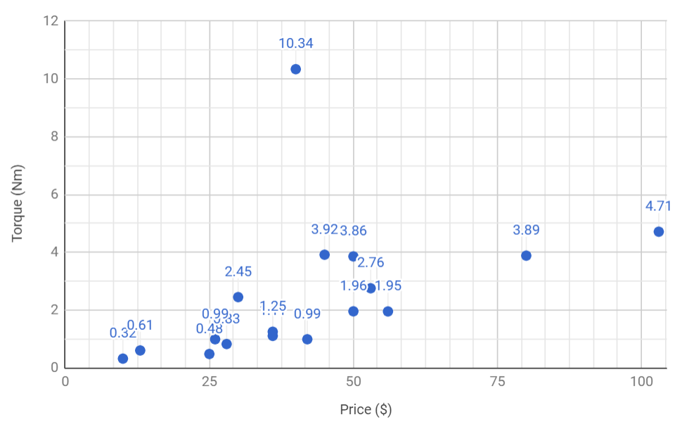
They cant get the hole spacing right in the specs, and the pictures vary within the same product… Most gimbals motors I’ve bought from them didn’t match either the pictures or the specs. Luckily, I was 3D printing/Laser cutting the mounts and the hole size and spacing was arbitrary.

If you want even more torque out of a cheap motor then take a look at the link below. I can’t say for sure that they are direct drive brushless motors but implies so by comparing them to gear motors:

http://www.cnqsmotor.com/en/article_read/QS%20Motor%2010inch%20500W%20-%204000W%20205%20E-Scooter%20Hub%20Motor/526.html

In fact they are definitely whopping great BLDC motors. See here:

https://endless-sphere.com/forums/viewtopic.php?f=31&t=65972

It looks the Star Wars Rebel Alliance logo

Hi, new guy, first post, please bear with me :slight_smile:

Why not drill a hole in the center of the rotor “cover”, and replace the shaft with a longer one, thus giving you double sided attachment to the structure of your robot arm?

Best regards
Asle Borgen,

The main reason I want to try the cantilever way is that it would mean there are less steps and easier for someone else to build.
Your suggestion is a good idea and is probably what I’ll try if the original way doesn’t work.

1 Like